This is a roll-up thread that should answer most if not all questions regarding power availability in the cab.
A lot of the credit for technical detail goes to @Jimmy07 without whose help and guidance much of this info would be hard to assemble.
There are other contributors, you know who you are. If you recognize a photo as one of yours, shoot me a PM and I'll add the credit.
All trucks
BAT+ 12V Constant power:
IGN/ACC 12V
For trucks equipped with Aux switches
Further details regarding AUX Switches - (post #5): https://hdrams.com/forum/index.php?threads/in-cab-power-faq.9711/post-181297
A lot of the credit for technical detail goes to @Jimmy07 without whose help and guidance much of this info would be hard to assemble.
There are other contributors, you know who you are. If you recognize a photo as one of yours, shoot me a PM and I'll add the credit.
All trucks
BAT+ 12V Constant power:
- Driver side under the dash panel. Red wire in connector (need reference and image) Pin #
- This is power for the overhead tailgate release button (if equipped) but present on all trucks. It's a 10A fused circuit only draw is for tailgate release.
- If equipped with the overhead tailgate release, this same Red wire has 12V constant power on the button connector.
- High current power is available at the HAPP under the hood - (post #7) https://hdrams.com/forum/index.php?threads/in-cab-power-faq.9711/post-181308
IGN/ACC 12V
- Passenger Side under the dash end panel. Pink/Yellow wire in Connector / Pin # (need reference and image)
- This wire is present in the overhead if you have at least an auto dim mirror.
- The top of dash 12V port is defaulted to BAT+ 12V but is controlled by the fuse in location F90/F91 and can be set for IGN.
- The connector plugged into the rear USB ports has both battery power and acc. The pink/yellow wire is acc, (same circuit as mirror) and the red wire is battery.
- If you have the wireless charger, it also has pink/yellow acc power.
- Under hood RUN/ACC, BAT power:
- PDC Connector C5, Pin 7 = Circuit F781 PK/YE, 10A (F65) - (USB Charging Port, Wireless Charging Module and the Invertor Module)
- PDC Connector C7, Pin 9 = Circuit F986 PK/YE, 20A (F90/91) - User selectable IGN/BAT
| F65 | / | ATR (Micro2) | 10 Amp Red | MOD Inverter (Wake Up) / Power Port / USB IP / WCPM – If Equipped (HD Only) Spare (DS 1500 Only) |
| F80 | / | ATR (Micro2) | 10 Amp Red | Universal Garage Door Opener / Compass / Anti-Intrusion Module (DS 1500 Only) ASSY Overhead Console / SW Assist / SW 911 – If Equipped (HD Only) |
| F90/F91 | / | ATR (Micro2) | 20 Amp Yellow | IGN or BATT Customer Selectable – If Equipped (HD Only) Power Outlet (Rear Seats) Customer Selectable (DS 1500 Only) |
| F104 | / | ATR (Micro2) | 20 Amp Yellow | Power Outlets (Instrument Panel / Center Console) / Trunk – If Equipped (DS 1500 Only) UCI Port / USB Rear (HD Only) |
For trucks equipped with Aux switches
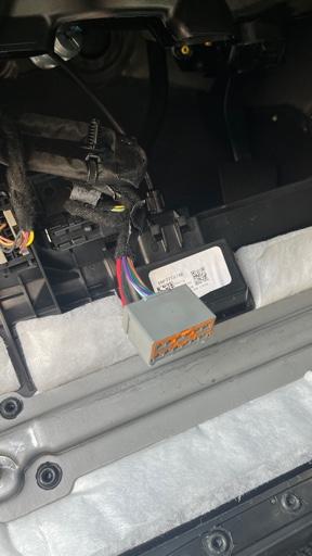
- There is a light gray jumper D2621A above the e-brake near the firewall that has BAT+ and IGN in addition to one or more pass through circuits depending on model year.
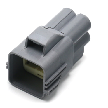
- Pass thru circuits are present in the AUX plugs under the hood.
- G425 VT/YE
- MY 21+ have 4 additional circuits on D2433A terminated on blunt cut wires near the PDC (see below)
- W550 BG/GY shown in the image below is not present on 2019-2020 trucks. This is a 21+ added pass-thru.
.
- Pass thru circuits are present in the AUX plugs under the hood.
- For 21+ trucks with Aux switches there is an additional white jumper D2433A with 3 pass through circuits that terminate at blunt cut wires near the PDC along with W550.
- W547 BG/DB
- W548 BG/BN
- W549 BG/DG
Further details regarding AUX Switches - (post #5): https://hdrams.com/forum/index.php?threads/in-cab-power-faq.9711/post-181297
Last edited: