So now, question: If I jumper AUX1 under the hood to the pass through under the hood and I plug in the grey jumper connection inside the cab against the firewall to put power to the back of my 2500, that then makes the wires at (F) at the rear of the truck active for use (mounting LED bed lighting that I want cab control over) so that when I find the wires (F) on top of the spare tire, I then want to connect my LEDs to the PK/OR ign wire I find there and connect the ground anywhere in the back on the frame. If I do that, I will be running the LEDs off the AUX1 switch? Making sure I've understood the videos and all your posts and diagrams correctly. Thanks guys.
No.
The wires at the back are by default BAT and IGN if you plug in the jumper. Nothing to do with AUX unless you change/cut wires.
If you want to send an AUX control back there, you would have to re-pin one of those to the pass-thru circuit and connect that to an AUX switch.
Which one do you want to use?
BAT converted to AUX?
or
IGN converted to AUX?
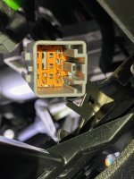
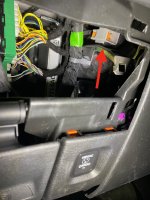
As an example. If you wanted to use the IGN wire (F606) on AUX1 instead of IGN, you would move the wire in pin6 to the pin 5 location (or cut and splice) and connect G245 VT/YE to the AUX1 plug. This would send the 12V from AUX1 using the F606 circuit on the cab side to the rear of the truck on the PK/OG wire. As a bonus, swapping pin 6 and 5 would give you IGN power on the VT/YE inside the cab.

Here's another way to look at it: