
I'm probably a bit late, but Wago Lever Nuts are the way to go. They're fairly common on boats, and Airstream uses them on their trailers.Yeah, honestly a little anxiety for me on those as well.
I figured if I borked it, I would fall back on soldering.
Definitely way open to suggestions.
This forum consistently restores my faith in humanity @John Jensen , many thanks!
Ram Heavy Duty Forum
You are using an out of date browser. It may not display this or other websites correctly.
You should upgrade or use an alternative browser.
You should upgrade or use an alternative browser.
In Cab Power FAQ -- AUX Switch power info -- Chassis power info
John Jensen
Well-Known Member
- Joined
- Feb 11, 2020
- Messages
- 1,206
- Reaction score
- 1,060
Didn't know about Wago Lever Nuts - look good. ThanksI'm probably a bit late, but Wago Lever Nuts are the way to go. They're fairly common on boats, and Airstream uses them on their trailers.
QuattroCS
Well-Known Member
didnt know that was the name of it,i have some and they do look good, thank youI'm probably a bit late, but Wago Lever Nuts are the way to go. They're fairly common on boats, and Airstream uses them on their trailers.
QuattroCS
Well-Known Member
interesting, i didn't know about those, thank you for sharingI like posi-tap connectors for stuff like that.
Bombaman
Active Member
- Joined
- Mar 17, 2022
- Messages
- 187
- Reaction score
- 247
I decided to hard wire my dash cam (Did my Wife's JL Jeep with the Aux switches, Jeep really hit the mark there, internal AUX switches come with a fused BAT and ACC wire in the bundle).
Anyway, following @Brutal_HO 's comment
"The connector plugged into the rear USB ports has both battery power and acc. The pink/yellow wire is acc, (same circuit as mirror) and the red wire is battery."
I removed my center console, very easy to do with a pry tool a 10mm and a 7mm, you don't need to remove the radio. Where the connectors are at the front has the BAT and Pink/Yellow accessory wire easily accessible at the bottom of the radio/manual controls.
Pulled the pins, cut and soldered in a new lead with some quick connect ends. Shortened the cables and USB lines on the VIOFO hardwire kit. Some Cloth elecrical tape for that OEM look and worked nicley!
Took it slowly, and even with "discovery" and a number of brewski's still done in under 2 hours.
Don't mind the adapters on the USB side of the Hardwire kit, I already had a USB C-USB A cable run from the camera, so just used a A->C adapter to connect.
Attachments
Brutal,Also correct. But as posted in #2, there's constant 10A fused power in the cab where indicated (still working on the connector/pin.)
Pass thru power, BAT or IGN would be good for higher loads.
There's an upfitter doc for picking BAT or IGN power off the bottom of the Primary PDC. I'll try to find that again and put it up. Also remember the jumper that brings BAT and IGN into the cab and back out to the rear frame can be used.
You could also fuse a wire directly off the HAPP.
Were you able to find the upfitter doc that you referenced above?
Brutal,
Were you able to find the upfitter doc that you referenced above?
I'll find the direct PDF link and add it to the first post, but here's the basics;
Connector C5, Pin 7 = Circuit F781 PK/YE
(ETA: It looks like F986 is fused by F90/91) which is selectable IGN/BAT) - could use verification form someone with TechAuthority access and more insight. @Jimmy07
Connector C7, Pin 9 = Circuit F986 PK/YE
"On all vehicles there are circuits are F781 and F986 (Run/Accessory feeds), on vehicles with auxiliary switches (standard on Cab Chassis and
optional on Pick Ups) there is and additional F606 a Run circuit. The F781 and F986 circuits are powered when the vehicle is in Accessory
or Run mode. The F781 circuit is fed by a 10A fuse that feeds several modules inside the vehicle (USB Charging Port, Wireless Charging
Module and the Invertor Module). The F781 circuit comes out of the bottom of the main power distribution center (PDC) in pin 7 of
connector C5. The F986 circuit is fed by a 20A fuse and feeds the Power Outlet inside the vehicle and comes out of the bottom of the main
PDC in pin 9 of connector C7. Unless using either one of the circuits to feed a low current device, we recommend using either of them to
control a relay with a fuse to provide the switched power."


Last edited:
PIN information for C7 showing F986
 connectors.dcctools.com
PIN information for C5 showing F781. The new part # for C5 is 68396629AB
connectors.dcctools.com
I don’t know if this helps with anything. I was just trying to figure out what the bottom of the
PDC looks like with these circuits coming out the bottom. Best I could come up with is this place where you can order a new PDC.
 circuitboardmedics.com
Sorry for the bad links. And they still show the C5 as AA not AB.
Mopar Connection Repair Kit
PIN information for C5 showing F781. The new part # for C5 is 68396629AB
Mopar Connection Repair Kit
I don’t know if this helps with anything. I was just trying to figure out what the bottom of the
PDC looks like with these circuits coming out the bottom. Best I could come up with is this place where you can order a new PDC.
2013 - 2019 Ram Power Distribution Center Repair
We offer a Dodge Ram Power Distribution Center/Module Repair Service for 2013-2019 models. Our repair is done in 1-business day and includes a 1yr warranty!
Sorry for the bad links. And they still show the C5 as AA not AB.
Last edited:
Wago connectorsYeah, honestly a little anxiety for me on those as well.
I figured if I borked it, I would fall back on soldering.
Definitely way open to suggestions.
This forum consistently restores my faith in humanity @John Jensen , many thanks!
spg993tt
New Member
- Joined
- Apr 11, 2021
- Messages
- 28
- Reaction score
- 19
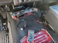
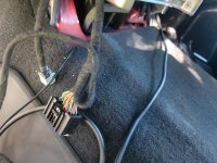
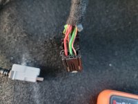
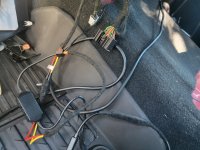
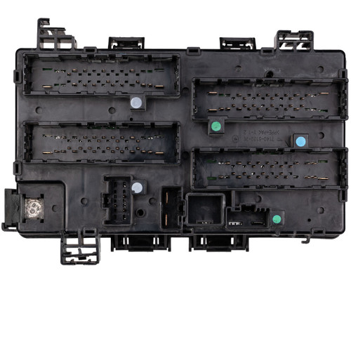
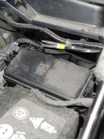
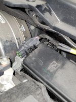
hoping someone might be able to give some advice on better accessing the light grey and dark grey connectors that are fixed to the PDC just rearward of the battery in the hood/engine compartment,. the connectors where we snap in the wires with metal blades. the two connectors on mine are angled down a ton, so kind of hard to access, see them, etc. looks like the two connectors sit on a molded plastic mount which seems to snap into a receiver on the pdc itself (at least I think that's the pdc with all the fuses for the aux buttons etc). i pushed that tab in and tried wiggling the connector holding assembly up, it seemed to start coming up ,and then hit solid resistance, cant see back there too well...figured before I wrench and really pull on it, I would just ask as maybe there is a simpler way. the one (top) cover of the connector came off but the lower connector I cant figure out how the cover releases and there isn't too much room to wiggle it off...it I couldn't I wouldn't release the two at all. so maybe that's question # 2, the lower of the two connectors... and lastly, I see the bundle of blunt cut/heat shrunk cables as well. i presume when I strip off the wrap at the end, they have colors to match the tails of the connectors in the cabin after in snap in the two harnesses inside under the dash??
more simply stated: how do I release those two connectors so I can access the a bit easier:? how do I get those outer cover off that connector into which I snap the bladed wire and 3) are those bundled wires colorized or notated so I don't have to strip all 4 to setup one pass thru?
tku!
more simply stated: how do I release those two connectors so I can access the a bit easier:? how do I get those outer cover off that connector into which I snap the bladed wire and 3) are those bundled wires colorized or notated so I don't have to strip all 4 to setup one pass thru?
tku!
Attachments
At post 5 of this thread, there is a video, at about the 3 minute mark, they show the connectors being removed.hoping someone might be able to give some advice on better accessing the light grey and dark grey connectors that are fixed to the PDC just rearward of the battery in the hood/engine compartment,. the connectors where we snap in the wires with metal blades. the two connectors on mine are angled down a ton, so kind of hard to access, see them, etc. looks like the two connectors sit on a molded plastic mount which seems to snap into a receiver on the pdc itself (at least I think that's the pdc with all the fuses for the aux buttons etc). i pushed that tab in and tried wiggling the connector holding assembly up, it seemed to start coming up ,and then hit solid resistance, cant see back there too well...figured before I wrench and really pull on it, I would just ask as maybe there is a simpler way. the one (top) cover of the connector came off but the lower connector I cant figure out how the cover releases and there isn't too much room to wiggle it off...it I couldn't I wouldn't release the two at all. so maybe that's question # 2, the lower of the two connectors... and lastly, I see the bundle of blunt cut/heat shrunk cables as well. i presume when I strip off the wrap at the end, they have colors to match the tails of the connectors in the cabin after in snap in the two harnesses inside under the dash??
more simply stated: how do I release those two connectors so I can access the a bit easier:? how do I get those outer cover off that connector into which I snap the bladed wire and 3) are those bundled wires colorized or notated so I don't have to strip all 4 to setup one pass thru?
tku!
Last edited:
Lucky Devil
Member
Does anyone know how/where to detect when each specific door is open? I know there are sensors somewhere because the instrument cluster shows which specific doors are open. (And the factory power steps can determine if a front and / or rear door is open on each side.) I want to use that to trigger some puddle lights when the doors open.
mountainears
Well-Known Member
- Joined
- Mar 29, 2022
- Messages
- 590
- Reaction score
- 440
If your truck has the VSIM installed or you add it there is a signal wire on the gray connector to tell you if ANY door is ajar, not a specific door. See page 5 #15
Sent from my iPhone using Tapatalk
Sent from my iPhone using Tapatalk
Lucky Devil
Member
If your truck has the VSIM installed or you add it there is a signal wire on the gray connector to tell you if ANY door is ajar, not a specific door. See page 5 #15
Sent from my iPhone using Tapatalk
Thanks, Mountainears. I know there's the any door option in the VSIM; I was trying to figure out if there's a way to figure out specific doors. I'm considering using magnetic reed switches (proximity switch), but they just look so chintzy. I really prefer an integrated factory-looking result, not bolt-on doo-dads!
Lucky Devil
Member
According to the diagram below (2022 3500 with bed and Aux switches), there is a CHMSL feed (letter M) on the frame near the right rear wheel. Is this in any way different than the stop light circuit (Wh/Pu wire) mentioned in @Brutal_HO post below?
Also, are any of these circuits fused in the PDC, or is it up to the upfitter to add fuses near the load? Specifically, the Rd/Wh Battery and Pk/Or Ignition vehicle wiring above the spare tire.

Thanks again for everyone's contributions to this thread. Very helpful!
Also, are any of these circuits fused in the PDC, or is it up to the upfitter to add fuses near the load? Specifically, the Rd/Wh Battery and Pk/Or Ignition vehicle wiring above the spare tire.
Q: Where are the blunt cut rear frame wires?
A: Above the spare tire.
RD/WH is 12V BAT
PK/OR is IGN
WH/PU is stop light circuit


Thanks again for everyone's contributions to this thread. Very helpful!
So if I'm reading this correctly. A regular HD truck w/ no upfitter or VSIM only has Constant 12V power on Driver side w/ 12VACC on passenger side? The first post says they are both up in the "overhead" but no single source on either side?
I am planning to use AUX6 along with the pass-thru for my BD 2-LO Unlock also - do you have any additional information or tips to share prior to me performing this?
Just patience manipulating the module harness and BD unit into place and getting the 12V lead over from the pass-through circuit to the BD unit.
I just really want to thank all you guys for contributing your expertise to this forum. I don't know if you know this, but in our RAM owners manuals (I own a 2021 2500 Tradesman), the section on AUX Switches refers you to the ramtrucks.com website so you can use the online builder's guide for more information. EXCEPT Stellaris has now restricted access to the website to commercial upfitters and you have to request access and justify why you need information that is SUPPOSED TO COME IN YOUR OWNERS MANUAL. So without you guys helping out your fellow DIYers, we'd really be screwed. I spent 30 minutes screaming at Chrysler customer service because they have no right to deny me access to information that I frankly paid for when I bought the darn truck and how dare they just because I don't manage a fleet of at least 5 vehicles. So forgive the rant, but I wanted to put that out there and again... thank you all.
So now, question: If I jumper AUX1 under the hood to the pass through under the hood and I plug in the grey jumper connection inside the cab against the firewall to put power to the back of my 2500, that then makes the wires at (F) at the rear of the truck active for use (mounting LED bed lighting that I want cab control over) so that when I find the wires (F) on top of the spare tire, I then want to connect my LEDs to the PK/OR ign wire I find there and connect the ground anywhere in the back on the frame. If I do that, I will be running the LEDs off the AUX1 switch? Making sure I've understood the videos and all your posts and diagrams correctly. Thanks guys.
Users who are viewing this thread
Total: 1 (members: 0, guests: 1)