
Obviously you like living on the edge. LOLI delivered some bales of straw to my daughter's preschool this week for halloween. Boy was I glad to have the high output dually for this load! I ran fast and reckless with no WDH, but I survived the trip.
View attachment 24398
Ram Heavy Duty Forum
You are using an out of date browser. It may not display this or other websites correctly.
You should upgrade or use an alternative browser.
You should upgrade or use an alternative browser.
My Big Booty Dually Adventure Rig Build
- Thread starter SFAngus
- Start date
PapaJoe
Member
- Joined
- Jul 13, 2021
- Messages
- 58
- Reaction score
- 90
I wonder just how many of those trailers loaded with straw bales he could tow ?? 15? 20? 25?Obviously you like living on the edge. LOL
SFAngus
Well-Known Member
So, here's the first of multiple updates for my 12v system in the bed of my truck.
My goal is to have a 12v power source in the rear of my truck, for powering/charging accessories and to power lights. I considered two main options for the power source:
1) Tapping into the 12v blunt-cut wire at the rear of the truck
2) Tapping into the 7-pin wiring plug that is located in the bed of the truck.
I opted to go with option number two, mostly because the power source was already exactly where I wanted it to be (located inside the storage cabinet of my carpet kit). I also figured that the supplied amperage from the 87-pin that is designed to charge an RV house battery would be more than enough to power my lightweight accessories.
I figured that worst case, if it doesn't work out, I can always tap into the blunt cut wire at a later date, and run it up into the bed after all the accessories are installed.
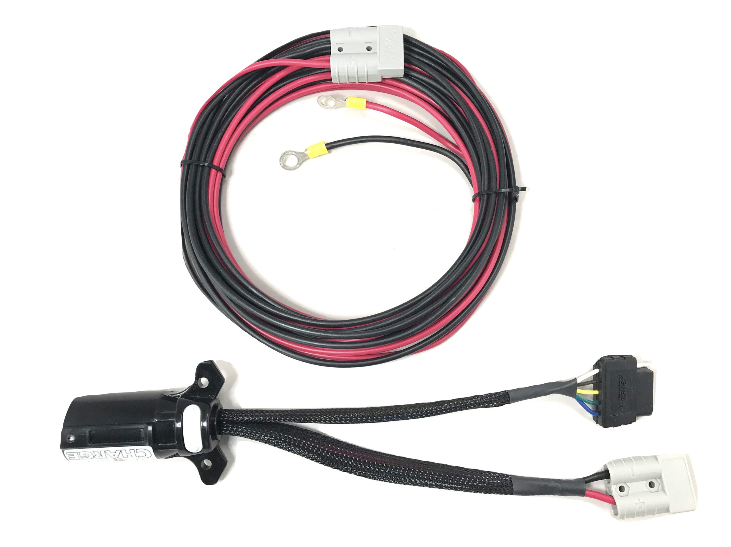
While poking around on the forums here, I saw someone (I can't remember where) mention the Curt 7-pin harness adaptor as an option. So, I picked one up on Amazon for about $26. (Side note- EZTopperLift sells a similar solution that comes with some nice wiring already set up including a detachable plug for $110. They call it the "Stow-in-charge" and it looks like a nice setup, but I didn't see the need to pay for their wiring connection.
 topperezlift.com
Here are the components that I decided to use:
-Curt 7 pin replacement harness
-Nilight 5 gang switch panel
-Dual USB/12v switched accessory panel
-6 way blade fuse box holder
-Nilight LED truck lights
(These items are listed on the first page of my build with associated links, if you're interested).


My goal is to have a 12v power source in the rear of my truck, for powering/charging accessories and to power lights. I considered two main options for the power source:
1) Tapping into the 12v blunt-cut wire at the rear of the truck
2) Tapping into the 7-pin wiring plug that is located in the bed of the truck.
I opted to go with option number two, mostly because the power source was already exactly where I wanted it to be (located inside the storage cabinet of my carpet kit). I also figured that the supplied amperage from the 87-pin that is designed to charge an RV house battery would be more than enough to power my lightweight accessories.
I figured that worst case, if it doesn't work out, I can always tap into the blunt cut wire at a later date, and run it up into the bed after all the accessories are installed.
While poking around on the forums here, I saw someone (I can't remember where) mention the Curt 7-pin harness adaptor as an option. So, I picked one up on Amazon for about $26. (Side note- EZTopperLift sells a similar solution that comes with some nice wiring already set up including a detachable plug for $110. They call it the "Stow-in-charge" and it looks like a nice setup, but I didn't see the need to pay for their wiring connection.
Stow-In-Charge - TopperLift
Truck camping with TopperLift. Live on the road, setup camp at the touch of the button.
topperezlift.com
Here are the components that I decided to use:
-Curt 7 pin replacement harness
-Nilight 5 gang switch panel
-Dual USB/12v switched accessory panel
-6 way blade fuse box holder
-Nilight LED truck lights
(These items are listed on the first page of my build with associated links, if you're interested).
SFAngus
Well-Known Member
I knew that I wanted to install the switches and accessories somewhere easily accessible, along the top of the carpet kit.


This location is also directly above the 7 pin outlet in the bed, which makes it convenient.

Testing placement for the switch panel and accessory panel:


This location is also directly above the 7 pin outlet in the bed, which makes it convenient.
Testing placement for the switch panel and accessory panel:
SFAngus
Well-Known Member
The first step was to figure out the wiring on the 7-pin harness. It was a lot less intuitive than I would have expected, and for some reason, there seemed to be a bunch of different wiring setups depending on which version of 7-pin you have. But, after a little research, and some trial and error on the 7-pin outlet at the bumper, I was able to determine which version I had, and which wire was which.
Contrary to what I would have expected, the 12v hot is black, and the 12v ground is white. I don't need the rest of the wires, (Turn signals, brakes, taillights, etc) so I wrapped them up nicely and tucked them out of the way.


Contrary to what I would have expected, the 12v hot is black, and the 12v ground is white. I don't need the rest of the wires, (Turn signals, brakes, taillights, etc) so I wrapped them up nicely and tucked them out of the way.
SFAngus
Well-Known Member
I did some youtube research, and picked up a few tips for wiring the switches. The 5-gang switch panel and the usb/12v accessory panel both come pre-wired, which is nice, except that each switch is daisy-chained onto the next. That means that the load is traveling through all of the switches.
Incorporating the accessory fuse box is probably overkill for my application, but I wanted to make it a robust system that can potentially handle higher loads in the future. (if nothing else, just to have the experience of doing it). It took a little bit of brainstorming as to the best way to incorporate everything, but this is what I came up with:
I separated each of the switches by cutting the wires running between them, and instead ran a new wire from the fuse panel up to each switch. That means that instead of having one power source feeding everything, each switch has its own separate, fused, 12v line. (With the exception of a couple of switches that pull from the same fuse, because the fuse box only has 6 fused outputs. For those switches, I am using them for the led lights, which will use a very minimal amperage and can share a fuse).

The second next goal that I needed to wrap my brain around was having a main power switch to everything. I was tempted to run the large 12v hot and 12v ground directly to the fuse box, but in that case everything would have had power running to it at all times. I wanted to be able to have a main power switch that would be easy to access. I decided to use the illuminated rocker switch that's built into the usb/12v accessory panel. Usually, this switch would just power the USB outlets, the built-in voltage gauge, and the 12v socket on that same panel. Since I had already decided to re-wire the switches, it wasn't a big deal to re-wire this one as well.

So, what I decided to do was run the 12v hot from the Curt harness directly to this blue switch, and then run the return line back to the fuse box, to power all of the fuses. The only downside of this setup is that all of the power is running through that switch, and because it's just a relatively cheap Amazon unit, I don't know how much amperage it's actually rated for. However, if this becomes an issue, (ie if the switch burns out), I can re-wire that part of it easily enough.
Since the blue rocker switch won't be powering the 12v and USB accessories on that same panel, I opted to run wires to two of the 5-gang switches to handle those duties.

Incorporating the accessory fuse box is probably overkill for my application, but I wanted to make it a robust system that can potentially handle higher loads in the future. (if nothing else, just to have the experience of doing it). It took a little bit of brainstorming as to the best way to incorporate everything, but this is what I came up with:
I separated each of the switches by cutting the wires running between them, and instead ran a new wire from the fuse panel up to each switch. That means that instead of having one power source feeding everything, each switch has its own separate, fused, 12v line. (With the exception of a couple of switches that pull from the same fuse, because the fuse box only has 6 fused outputs. For those switches, I am using them for the led lights, which will use a very minimal amperage and can share a fuse).
The second next goal that I needed to wrap my brain around was having a main power switch to everything. I was tempted to run the large 12v hot and 12v ground directly to the fuse box, but in that case everything would have had power running to it at all times. I wanted to be able to have a main power switch that would be easy to access. I decided to use the illuminated rocker switch that's built into the usb/12v accessory panel. Usually, this switch would just power the USB outlets, the built-in voltage gauge, and the 12v socket on that same panel. Since I had already decided to re-wire the switches, it wasn't a big deal to re-wire this one as well.
So, what I decided to do was run the 12v hot from the Curt harness directly to this blue switch, and then run the return line back to the fuse box, to power all of the fuses. The only downside of this setup is that all of the power is running through that switch, and because it's just a relatively cheap Amazon unit, I don't know how much amperage it's actually rated for. However, if this becomes an issue, (ie if the switch burns out), I can re-wire that part of it easily enough.
Since the blue rocker switch won't be powering the 12v and USB accessories on that same panel, I opted to run wires to two of the 5-gang switches to handle those duties.
SFAngus
Well-Known Member
Once I had a decent idea of how I wanted things to be wired, I decided to go ahead and cut into the plywood/carpet kit to get everything mocked up. I used a combination of a power drill, Sawzall, and Dremel to get the holes cut out to the proper size. I took loose measurements, but honestly it was mostly eyeballed, and luckily it came out well.
The one rookie mistake I made was not holding the carpet in place enough while I was initially drilling. The bit grabbed onto the carpet and twisted it, separating it away from the plywood too much. I was able to fix this easily at the end by using a little bit of wood glue to reattach it.


My workshop:

Both panels mocked in:

The one rookie mistake I made was not holding the carpet in place enough while I was initially drilling. The bit grabbed onto the carpet and twisted it, separating it away from the plywood too much. I was able to fix this easily at the end by using a little bit of wood glue to reattach it.
My workshop:
Both panels mocked in:
Last edited:
That came out really nice! Great work!!Once I had a decent idea of how I wanted things to be wired, I decided to go ahead and cut into the plywood/carpet kit to get everything mocked up. I used a combination of a power drill, Sawzall, and Dremel to get the holes cut out to the proper size. I took loose measurements, but honestly it was mostly eyeballed, and luckily it came out well.
The one rookie mistake I made was not holding the carpet in place enough while I was initially drilling. The bit grabbed onto the carpet and twisted it, separating it away from the plywood too much. I was able to fix this easily at the end by using a little bit of wood glue to reattach it.
View attachment 24435
View attachment 24437
View attachment 24438
My workshop:
View attachment 24436
Both panels mocked in:
View attachment 24439
Greg
2019 | RAM 2500 | CCSB | 6.4 HEMI
2016 | Heartland Pioneer | DS310
68vertvetty
Member
- Joined
- May 22, 2021
- Messages
- 13
- Reaction score
- 36
Your Ram is looking good!!! Do you have a picture of the CB radio after you installed it?
SFAngus
Well-Known Member
Your Ram is looking good!!! Do you have a picture of the CB radio after you installed it?
Thanks! I can get a photo for you, but it's not properly mounted yet. I just have it tucked into the pocket on the side of the center console for now. It actually fits because of how small it is, but it's nothing fancy.
Unfortunately the display screen on the President CB hasn't worked since I bought it, and I've had no luck reaching anyone for support. It's been a low priority, but hopefully I'll get it sorted out eventually.
SFAngus
Well-Known Member
I sold the truck, sadly, but I'm finally getting around to making some YouTube videos to document some of the modifications. If you're interested in checking out the ProClip phone mount, here's a video:
aaronedmonton
Well-Known Member
- Joined
- Sep 5, 2021
- Messages
- 177
- Reaction score
- 264
Curious as to why you sold the truck, if you don’t mind sharing.I sold the truck, sadly, but I'm finally getting around to making some YouTube videos to document some of the modifications. If you're interested in checking out the ProClip phone mount, here's a video:
SFAngus
Well-Known Member
Curious as to why you sold the truck, if you don’t mind sharing.
I have a 4th child arriving in two weeks, so I needed more seats. I hated to sell it, but I couldn't justify keeping it for the amount that I was using it. I ended up trading it in for $82k. I had it listed for about two months looking for a private sale, and got almost no bites on it. I think I missed the boat on the high demand for these earlier this year. If I had sold it back in March or April I probably could have gotten $90-95k for it. Oh well... It was a great truck, and I loved the use I got out of it.
I traded it in for a conversion van, which will be a fun project. I've never owned one before. Here's a video of the van:
Unfortunately, the van isn't 4wd, so I am planning on picking up an older Lexus LX470 that my neighbor is selling, to have a 3-row 4x4 for trips to the snow.
SFAngus
Well-Known Member
I've seen a lot of people asking questions on here about wiring the Aux Switches, specifically with the pass-through wiring. I made this video to document how I did it on my truck, to hopefully help those who would like to do it and are trying to figure it out.
Beautiful truck. I live in Fort Worth and drove to that dealer a couple of years back when I was in the market. They were rude and not willing to deal.
Need to replace those tires as soon as you are able, they are junk. The belts seperated on my front tires with 18,000 miles on them the day after I towed my 5er. Could of been really bad if that happened while towing.
Need to replace those tires as soon as you are able, they are junk. The belts seperated on my front tires with 18,000 miles on them the day after I towed my 5er. Could of been really bad if that happened while towing.
Users who are viewing this thread
Total: 1 (members: 0, guests: 1)