I still haven’t figured out who came up the idea of having to waste our time doing something for someone else, so that we will have the means to be able to waste more of our time doing something for ourselves. Damn them!  Seriously though, it’s looking awesome, I’m so jealous.
Ram Heavy Duty Forum
You are using an out of date browser. It may not display this or other websites correctly.
You should upgrade or use an alternative browser.
You should upgrade or use an alternative browser.
4500 Camper/Jeep Hauler Build
- Thread starter gprguy
- Start date
-
- Tags
- 4500 camper chassis cab jeep
gprguy
Well-Known Member
Love seeing your updates, looking great. Serious question and sorry if I missed the answer upthread: What is the purpose of this shape, if for lighting or camera, wouldn't it be blocked by the camper?
Thanks - it is for both, in the form of the stock CHMSL with the cargo camera and the DRVM cameras. The DRVM camera will let me see through the cargo box when the camper is off, and when the camper is on I'll plug in the trailer DRVM camera that will be mounted on the back of the camper so I can see through the camper too.
Brilliant!Thanks - it is for both, in the form of the stock CHMSL with the cargo camera and the DRVM cameras. The DRVM camera will let me see through the cargo box when the camper is off, and when the camper is on I'll plug in the trailer DRVM camera that will be mounted on the back of the camper so I can see through the camper too.
gprguy
Well-Known Member
Honestly it is one of the things I am looking forward to most on this build. I may put another DRVM trailer camera on the back of our cargo trailer as well (along with the trailer 360 cameras) so when we are also towing that one can be hooked up instead. So many toys!
gprguy
Well-Known Member
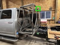
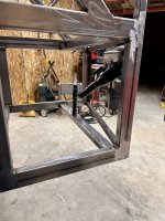
Managed to make some more progress over the last couple days. The driver's side compartment is built. I even remembered to take a few progress pics.
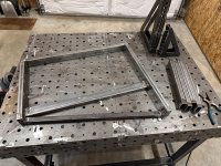
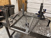
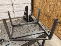
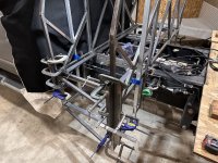
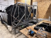
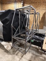
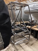
I think the plan from here is to lift it off the truck, get it back on the welding table so I can finish weld the uprights on the lower boxes, and then start figuring out where all the components that live in the boxes go so I can build brackets.
Starting to see the light at the end of the tunnel for the framework at least. I just looked back and it's only been just over a month since I abandoned the aluminum frame and started on this, but I really need to pick up the pace somehow. Getting it off to powder coat will be a major milestone.
gprguy
Well-Known Member
Overdue for an update I am sure. The box is back off the truck and on the welding table, and the lower parts are finish welded. No pics of that because it's boring.
One of my goals for this box was to integrate the DEF filler. I was hoping to do something better than leave it on the stock bracket, although it's yet another thing that's probably over complicated and not worth the expense.. So let's get to it!
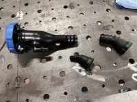
Here's the stock filler disassembled, and I've already cut the tubing off the quick connects that attach to the tank.
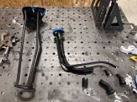
The stock tubing is some kind of heat shrink tubing, it's just shrunk over barb fittings. Ram actually has a document on extending the DEF filler if you look hard enough on the bodybuilder site, it's one of the pages in the box off document.
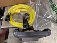
The trick is finding the right tubing to replace the stock tubing. Apparently the urea in DEF is pretty aggressive to most rubber, so normal fill neck hose that's resistant to gas/diesel won't do. It is possible to get "DEF transfer hose" but pretty much everywhere I looked was either out of stock or you had to buy at least 100'.
The Ram document mentions to use "commercially available Tygon tubing" so naturally that led me to Tygon MSDS sheets and eventually good old McMaster-Carr. It seems that most all Tygon tubing has excellent resistance to urea. The vent needs 1/2" ID tube, and the fill needs at least 7/8" ID but 1" would be easier to get over the barb.
In the end I bought F-4040-A tube for the vent, and I would have liked to also use F-4040-A for the fill because it is also oil resistant (not that that is needed for this application) but the largest it comes in is 3/4". I ended up buying 7/8" E-3603 for the fill. I would have liked to have gone with 1", however McMaster doesn't sell that in a 5 foot length - have to jump up to 10 feet and at around $10/ft that's money I don't need to spend. Long story short, the 7/8" will fit but it takes a lot of effort.
Alright, enough about expensive hose. How do we mount the fill neck - there's a lot of angles involved here, including that the fill neck has to be at a 30 degree tilt per Ram's specs. Off to Fusion360 to build a sheet metal fill neck surround.
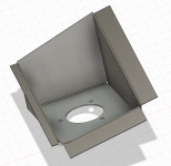
I printed it out at 2/3rds scale so it would fit on the paper and do a sanity check on some of the angles.
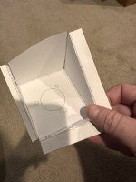
Turns out I didn't have it perfect, but it was close enough in the end. Off to the CNC plasma table to cut it out of 16 gauge steel. The table I have access to is in bad need of some adjustment and maintenance (I'm working on that too) so the corners are a little ragged, but it's close enough.
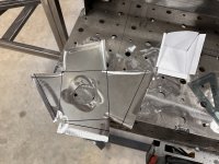
This is a really difficult shape to bend up, at least on the box brake I have. The flanges on the outside ended up being a bad idea, I tried to make them work but in the end I made a frame out of 1" square tube and chopped the flanges off. Many, many hours later here's the first time I am getting it to fit half decent.
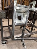
Tacked in place and test fitting the fill neck.
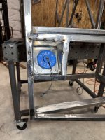
Much welding and grinding later and I am pretty happy with the result.
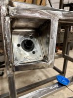
The hose will be routed through the skin and over to the tank. The fill neck is in basically the same height as before, just moved rearward a bit.
One of my goals for this box was to integrate the DEF filler. I was hoping to do something better than leave it on the stock bracket, although it's yet another thing that's probably over complicated and not worth the expense.. So let's get to it!
Here's the stock filler disassembled, and I've already cut the tubing off the quick connects that attach to the tank.

The stock tubing is some kind of heat shrink tubing, it's just shrunk over barb fittings. Ram actually has a document on extending the DEF filler if you look hard enough on the bodybuilder site, it's one of the pages in the box off document.

The trick is finding the right tubing to replace the stock tubing. Apparently the urea in DEF is pretty aggressive to most rubber, so normal fill neck hose that's resistant to gas/diesel won't do. It is possible to get "DEF transfer hose" but pretty much everywhere I looked was either out of stock or you had to buy at least 100'.
The Ram document mentions to use "commercially available Tygon tubing" so naturally that led me to Tygon MSDS sheets and eventually good old McMaster-Carr. It seems that most all Tygon tubing has excellent resistance to urea. The vent needs 1/2" ID tube, and the fill needs at least 7/8" ID but 1" would be easier to get over the barb.
In the end I bought F-4040-A tube for the vent, and I would have liked to also use F-4040-A for the fill because it is also oil resistant (not that that is needed for this application) but the largest it comes in is 3/4". I ended up buying 7/8" E-3603 for the fill. I would have liked to have gone with 1", however McMaster doesn't sell that in a 5 foot length - have to jump up to 10 feet and at around $10/ft that's money I don't need to spend. Long story short, the 7/8" will fit but it takes a lot of effort.

Alright, enough about expensive hose. How do we mount the fill neck - there's a lot of angles involved here, including that the fill neck has to be at a 30 degree tilt per Ram's specs. Off to Fusion360 to build a sheet metal fill neck surround.

I printed it out at 2/3rds scale so it would fit on the paper and do a sanity check on some of the angles.

Turns out I didn't have it perfect, but it was close enough in the end. Off to the CNC plasma table to cut it out of 16 gauge steel. The table I have access to is in bad need of some adjustment and maintenance (I'm working on that too) so the corners are a little ragged, but it's close enough.

This is a really difficult shape to bend up, at least on the box brake I have. The flanges on the outside ended up being a bad idea, I tried to make them work but in the end I made a frame out of 1" square tube and chopped the flanges off. Many, many hours later here's the first time I am getting it to fit half decent.

Tacked in place and test fitting the fill neck.

Much welding and grinding later and I am pretty happy with the result.

The hose will be routed through the skin and over to the tank. The fill neck is in basically the same height as before, just moved rearward a bit.

gprguy
Well-Known Member
Done. The flange on the left is a little messy, but that will be covered by the box's skin. Most of this will actually other than the recessed part.
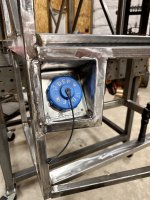
The good news is that is the last complicated job on the frame (the skin is another matter..). I need to add some flanges here and there to mount the skin to, and add the brackets to hold all the air and hydraulic things. Getting ever closer to sending it off for powder coating.

The good news is that is the last complicated job on the frame (the skin is another matter..). I need to add some flanges here and there to mount the skin to, and add the brackets to hold all the air and hydraulic things. Getting ever closer to sending it off for powder coating.
G Mcpherson
Well-Known Member
I am not sure if there would be a contamination issue, but possible use of some light soapy water on the Barb ends and the hose will be easier to slide on.
gprguy
Well-Known Member
I may use some silicone spray on the other end. By the time I got far enough to regret it on the end I already did I was committed.I am not sure if there would be a contamination issue, but possible use of some light soapy water on the Barb ends and the hose will be easier to slide on.
G Mcpherson
Well-Known Member
The soapy liquid I would think is less of a Contamination and would not retain the Lubricity of the Silicone. I have used this method with Pushlok fittings without issue.
Great White North Eh
Squish Cat - And So
- Joined
- Nov 10, 2019
- Messages
- 1,739
- Reaction score
- 2,867
Good job puttin the round peg in the square hole. 
gprguy
Well-Known Member
Quick mid-week update. The good news is with any luck the tedious part of the fabrication on the box is done, I finished all the lips and flanges I think I will need to attach the skin.
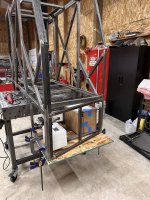
Now what's left is making mounts and brackets for all the heavy things that will go in the two compartments. Lighter stuff I can add rivnuts later after powder coating.
The passenger side is pretty well set, I think this is the plan. There's going to be 8 hydraulic hoses going to that pump so I need some space for all of that.
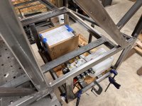
The driver's side I am still figuring out. This is what needs to go in here, but I am not sure I like the position of the Multiplus II (currently represented by a cardboard box).
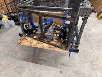
It's too big to go along the back wall, so it's either where it is on the inner wall or I'm going to need to build a separate shelf for it above the air components. I'm going to figure out what that looks like tomorrow and if it's any better.
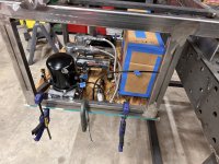
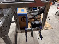
Or I might put the Multiplus flat on the bottom and mount the other components to the sides and hanging from the top. Need to do some more thinking for sure.

Now what's left is making mounts and brackets for all the heavy things that will go in the two compartments. Lighter stuff I can add rivnuts later after powder coating.
The passenger side is pretty well set, I think this is the plan. There's going to be 8 hydraulic hoses going to that pump so I need some space for all of that.

The driver's side I am still figuring out. This is what needs to go in here, but I am not sure I like the position of the Multiplus II (currently represented by a cardboard box).

It's too big to go along the back wall, so it's either where it is on the inner wall or I'm going to need to build a separate shelf for it above the air components. I'm going to figure out what that looks like tomorrow and if it's any better.


Or I might put the Multiplus flat on the bottom and mount the other components to the sides and hanging from the top. Need to do some more thinking for sure.
Bigboom338
Member
I know that you have a ways to go before you are completely finished with this build, but you should start thinking about what your next project is going to be. You are going to go through some serious withdrawal when you are done with this.
Great work.
Great work.
gprguy
Well-Known Member
Thanks - but no worries there, I've got a list a mile long...I know that you have a ways to go before you are completely finished with this build, but you should start thinking about what your next project is going to be. You are going to go through some serious withdrawal when you are done with this.
Great work.
gprguy
Well-Known Member
They can, although at least in my experience with our older Multiplus it takes either a high inverter load (such as running the AC) or a recharge from shore power after a deep discharge. I expect the vast majority of the time the multiplus won't be doing anything.How do you plan to vent for the MP-II? Those things can generate a lot of heat. Also, where are the house batteries going?
The box itself has a very large air volume (larger than most compartments I've seen Victrons installed in fifth wheels), it will have two 4x4" vents in the front for intake and air pressure equalization on the front similar to the cab rear vents, and beyond that I am curious to see how it does as well. If I have to I can add a powered exhaust fan on the roof or something like that.
The house battery (280ah 12v) is the cardboard cube on the passenger's side next to the hydraulic unit. If I feel like I want more (unlikely I think) I can add another under the flatbed in the future.
The whole idea of adding the inverter/battery is because there is room (I considered putting the air tanks internal to the box, but that just seems wasteful when there are other places). It will be nice for the convenience of 120v onboard, I can charge the e-bikes via their standard chargers (I know, converting 12v to 120v to 48v is silly and inefficient, but it preserves the warranty), and it can also be a range extender for the camper via either a DC/DC connection or even by plugging the camper shore power into the truck.
gprguy
Well-Known Member
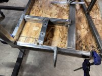
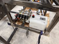
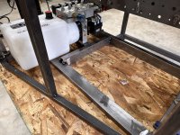
More brainstorming/fiddling and I think I have a better layout for the components.
On the passenger side, I swung the battery around 90 degrees and moved one of the compressors over there.
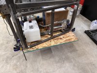
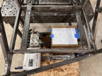
That freed up enough space on the driver's side to move the inverter to the floor and rearrange the other stuff a bit.
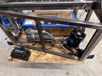
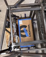
Last I noticed the manifold tucks in really nicely between the DEF filler and the upright, so I'll build a little shelf for it to sit on there (aluminum for mock up, will be steel).
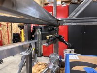
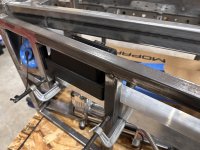
Unless I come up with another idea tomorrow I think this is the winner and I'll start making brackets. It leaves enough room between things and should allow me room to run all the cables and hoses without a complete spaghetti mess, and I think I should be able to remove any of the components out of the top even with the slide installed. Probably.
On the passenger side, I swung the battery around 90 degrees and moved one of the compressors over there.


That freed up enough space on the driver's side to move the inverter to the floor and rearrange the other stuff a bit.


Last I noticed the manifold tucks in really nicely between the DEF filler and the upright, so I'll build a little shelf for it to sit on there (aluminum for mock up, will be steel).


Unless I come up with another idea tomorrow I think this is the winner and I'll start making brackets. It leaves enough room between things and should allow me room to run all the cables and hoses without a complete spaghetti mess, and I think I should be able to remove any of the components out of the top even with the slide installed. Probably.
