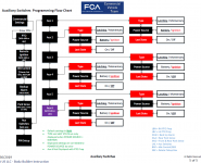
Keep in mind that the “last state” setting is only selectable when that switch’s power state is set to “ignition”.here is the imnage. some bizarre behavior. when i went thru commercial settings just now, to get you the photo, aux1 looked like it could infact now allow a Last State change to on. earlier today both AUx1 and 2 were greyed out onthe Last State toggle. the rest were able to be edited, and aux 3 4,5 i was able to change Last=On. i then moved the connector wire from port 1 to port 3. so all resolved for me that way just using aux3 for the radar control though it comes on all the time, a quick push of the aux button to turn it off when noisy.
anyway when i went to snap the photo of the greyed out Last State, Aux 1 looked like it was editable. wasnt greyed out. Aux 2 still was, see image.
aux 3 looked fine, in the On position, and editable. see the message it gives, cant tell if that something where the computer needs to see the load and 'approve it' but when i the wire into port 1 aux 1, it wouldnt allow it. or i needed to let it run for a while to let the computer monitor it??? i have no idea.
but a bit all over the place, and since im up and running on 3, as much as i normally dig tracing and bugging this stuff, i have no interest here. 1 is now editable, 2 which has nothing in it except the extra spare wire i ran into port2/aux 2 but has electrical tape on the end with nothing connected in the cabin..that is greyed out cant edit, thats where the message below comes from. and 3 where my radar now resides is also editable.
wierd.
Ram Heavy Duty Forum
You are using an out of date browser. It may not display this or other websites correctly.
You should upgrade or use an alternative browser.
You should upgrade or use an alternative browser.
AUX pass-thru wiring.
- Thread starter Xflight29
- Start date
Keep in mind that the “last state” setting is only selectable when that switch’s power state is set to “ignition”.
I was starting to think the same thing.
The Aux switches factory default come set to different settings. Some BAT+, some IGN.
spg993tt
New Member
- Joined
- Apr 11, 2021
- Messages
- 28
- Reaction score
- 19
1 and 2 set to battery by default. maybe thats it. ill look at aux 2 tomorrow and try it again. that would be easy enough to test out. i remember a day when toyota and the tundra technologies outpaced ford, ram/dodge and chevy by 5 fold. some of this stuff , and the dash, the uconnect, ...very slicks. they've come a long way.
spg993tt
New Member
- Joined
- Apr 11, 2021
- Messages
- 28
- Reaction score
- 19
yup, that was it.Keep in mind that the “last state” setting is only selectable when that switch’s power state is set to “ignition”.
Will_T
Well-Known Member
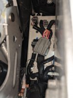
I believe I have the four blunt cut bundle located but I have not tested where the other end is yet as I am having trouble under the dash. See 1st photo which is, I believe the 4 wires Brutal refers to. But I don't find the other end of those 4 wires under the dash?Look at my edited post. There should be FOUR new pass-thru wires. Probably just blunt cut taped up in a bundle.
But the only connector I can find under the dash by the parking brake and steering column is what is pictured in the 2nd photo. That was taped way up in a spot uncomfortably small for my hands but I managed to move it a few inches to get a better look. It does not look to me like this is what RAM describes in the schematic as "D", "Port Upfitters Connecters, Under Dash Board near park brake bracket / Steering Column"? Or is it?? It does not look like the 12 gauge connector I found in the upfitters bag (photo 3), will fit into it, but maybe it will.
But if photo #2 is the correct socket for the wires with connector in photo 3, than why does photo 3 have wires in all 6 spots where as that connector in photo 2 only has 3 wires into the back. I see that there are two wires looped on the photo 3 plug and then two blunt cut wires. I am confused as to why that is? What are the two looped wires for? I am not good enough reading the schematic to figure it out so if someone could explain I would appreciate it. I thought I had found the answer in an earlier post in this thread but after reading it a couple of times, I still don't think I get it. Thanks.
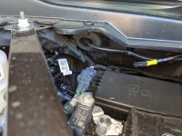
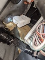
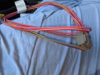
On edit: I found another connector that looks more promising. It was staring me in the face almost too obvious to miss, but I did. It is the gray one shown in photo 4 below. Is that what the wire connector in photo 3 plugs in to? And I still have not figured out the answers to the original questions above. Thanks again for educating a schematic dummy.
Last edited:
Will_T
Well-Known Member
@spg993tt I am not understanding all you wrote but I have gone over that PDF several times and still confused. Maybe just need to do it several more times.
Here are a couple more photos of the rest of what was in the bag I got. The 12 gauge 1/4" blade connectors in the first photo (5) I believe are for the upfitter receptacles under the hood. In the 2nd photo (6) is all the rest of what was in the bag. What are each of those pieces for? The two small plugs in the center just have loops connected to them. The one on the right has 12 gauge wires except for one smaller wire. The wires on the left are much smaller gauge and smaller blades. I did not think any of the four items in that photo were for the upfitter switches. Are you saying they are?
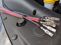
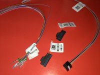
Here are a couple more photos of the rest of what was in the bag I got. The 12 gauge 1/4" blade connectors in the first photo (5) I believe are for the upfitter receptacles under the hood. In the 2nd photo (6) is all the rest of what was in the bag. What are each of those pieces for? The two small plugs in the center just have loops connected to them. The one on the right has 12 gauge wires except for one smaller wire. The wires on the left are much smaller gauge and smaller blades. I did not think any of the four items in that photo were for the upfitter switches. Are you saying they are?


Will_T
Well-Known Member
So maybe the white connector I found in photo 2 above is what the black connector on the right of photo 6 plugs in to? They didn't look like a match at first look but maybe they are.but there are two connectors under neath the dash, and then you have 2 plugs/connections/jumpers in your upfitter bag with the wires. those plug into the connectors, and then now you have a connection from under the hood, into the cabin.
those pass thrus go to the white or grey connector under the dash and thus to the wires that come off the cable/connector you snap into them.
Will_T
Well-Known Member
I printed out this thread and all the linked PDF's so I could spend the last 2 hours reading it the old fashioned way. I understand it much better now and tomorrow will make another attempt to get this set up. For some reason I seem to absorb this stuff easier from paper in hand rather than paging through a thread on the screen. 
Last edited:
Will_T
Well-Known Member
Got this more than 1/2 done today if you include all the time scrutinizing the schematics. Only had to use one "phone a friend". Thanks @spg993tt All the under hood and under dash wires are done and labeled. I should have all the switched power I want in the cab now.
I am not sure of the use of the wire on port 4 of the light gray connector, (G425) VT/YE, or about the use of the blunt end pass through W550?
I also did not look for the two wires under the rear of the truck yet. I have a use for the ignition switched wire back there if I can find it, but for now at least can't think of a use for the battery wire. I don't think I fully understand those rear wires yet or why they loop in the connector under the dash. If RAM wanted an ignition wire and a battery wire at the rear of the truck, why take them under the dash? Why not just run them straight back there? I guess I do not yet understand that routing and loops or their use yet. Anyone have a hint as to what I am missing on that part?
Last edited:
G425 is so you can bring a switch output in the cab without pulling wires through the firewall. Same with w550. That’s the beauty of how they set the up fitter wiring up- you should be able to do whatever you want, have accessories configured to operate however you want, without having to run any lengths of wire from the cab to the aux PDC, or from the rear all the way to the front. If you want something in the rear to run on constant battery, you can. If you want something in the rear to be on anytime the ignition is on, you can do that. Or, you use the jumper loops to configure one of those wires in the rear to be on an aux switch. I don’t know why it took them till the 21s to utilize empty connector positions to have the blunt cut wires pass from the cab to the engine bay. As long as you understand how the output connectors at the PDC work, and how to switch pass through jumper wires around, your options are pretty wide open.
Will_T
Well-Known Member
This is what I need to figure out. I could live with one of the rear wires, (once I find them), being ignitions switched, but ideally I would have one of the aux switches control one of those rear wires.Or, you use the jumper loops to configure one of those wires in the rear to be on an aux switch.... As long as you understand how the output connectors at the PDC work, and how to switch pass through jumper wires around, your options are pretty wide open.
Will_T
Well-Known Member
I could use some help, or a photo if someone has one, to locate the two blunt cut wires at the rear of the frame, "F" on the schematic below. I have looked all over the area for a long time now and can not find them. There are lots of wires in the vicinity but all are connected, no blunt cuts that I have found. I am about to lower the spare to look for the stop lamp wire that is at location "M" so maybe I will find the upfitter blunt cuts there also but that is clearly not where location "F" is in the diagram.
Thanks for any guidance as to exactly where they are or look like. I am about to give up on those in frustration.

Removed the spare and the 3rd brake wire was right where the diagram showed it to be at location "M". There are two other wires there, one 12gauge, the other maybe 16 gauge. What are those for? They would not be the two wires from the front I am looking for as those both would be 12 gauge. I still can not find those even with the spare off.
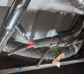
Thanks for any guidance as to exactly where they are or look like. I am about to give up on those in frustration.

Removed the spare and the 3rd brake wire was right where the diagram showed it to be at location "M". There are two other wires there, one 12gauge, the other maybe 16 gauge. What are those for? They would not be the two wires from the front I am looking for as those both would be 12 gauge. I still can not find those even with the spare off.

Last edited:
Will_T
Well-Known Member
OK, so for anyone else that is confused and looking for the rear frame wires from the upfitter system, they are those other two in the photo with the brake light wire. Not sure why RAM put them at location "M" rather than at "F" as the schematics show. Also not sure why one is only 16 gauge. Because of those two factors, I did not even consider them being what I was looking for. But on my truck once the upfitter plugs are connected, the 12g wire is always on battery power and the 16 gauge wire is ignition switched run power. Thanks to @thestuarts for mentioning in another thread that they found a smaller wire in the pair on their truck also. Although in his case, the smaller wire was the always on battery power wire not the the ignition "run" wire like mine.
Ramit530
Active Member
Great video @thestuarts and all the assistance, comments and feedback from all the members that chimed in here.
OK, so for anyone else that is confused and looking for the rear frame wires from the upfitter system, they are those other two in the photo with the brake light wire. Not sure why RAM put them at location "M" rather than at "F" as the schematics show. Also not sure why one is only 16 gauge. Because of those two factors, I did not even consider them being what I was looking for. But on my truck once the upfitter plugs are connected, the 12g wire is always on battery power and the 16 gauge wire is ignition switched run power. Thanks to @thestuarts for mentioning in another thread that they found a smaller wire in the pair on their truck also. Although in his case, the smaller wire was the always on battery power wire not the the ignition "run" wire like mine.
Thanks for this. However, if you use the jumper for upfitter, either of those become whatever you want, correct?
Correct. You can repin the jumper loops however you want to achieve whatever setup you want.Thanks for this. However, if you use the jumper for upfitter, either of those become whatever you want, correct?
I've got to wire a pass thru to run my two-way radio and phone booster and was wondering what you guys have been using as the ground for those pass thrus under the dash. I also will be running a light bar and possibly some other accessories under the hood to my aux plugs. Where do you recommend i ground under the hood?
Will_T
Well-Known Member
Thanks for this. However, if you use the jumper for upfitter, either of those become whatever you want, correct?
Correct. You can repin the jumper loops however you want to achieve whatever setup you want.
The thing that some of the people that are experienced and good with all this might not realize is: For some of us this is the first time we have done this. For example, repinning is mentioned and looking at the schematics and the wires actually one the truck, I can likely figure out which wires to change. But first I have to figure out how to just get a wire out of one of these connectors so another can replace it. I have never repined anything before and never even saw one of these connectors before taking on setting up the upfitter switches. Such basic stuff, the experts here may not even realize where some of us are starting from. Of course with the gracious help of people like Jimmy and others we can be successful. I now have several switches working for things in the cab, plus one for under the hood. Hopefully tomorrow I will get one more working at the back of the truck using the 12g wire RAM installed. (If I can figure out how to depin and repin the connectors once I take a close look).
Last edited:
Will_T
Well-Known Member
I've got to wire a pass thru to run my two-way radio and phone booster and was wondering what you guys have been using as the ground for those pass thrus under the dash. I also will be running a light bar and possibly some other accessories under the hood to my aux plugs. Where do you recommend i ground under the hood?
I am not sure if it was the best way to do it, but for now I attached a ground bus bar under the dash to use. Grounded the bar with 12g wire to metal that appears to give a good ground. Tested it and it seems good. I have connected a couple of 12v to 5v step down converters for power to a dash cam and a trailer rearview camera. Fortunately somehow I knew that devices with OEM cigarette lighter type plugs can not be just direct wired to 12 volts.
For ground under the hood I am connecting to screws or bolts already attached to the frame. Again not sure if it is the best way, but it works.
Users who are viewing this thread
Total: 2 (members: 0, guests: 2)
