
I got the same thing you do. Have you figured it out?So I've been contemplating adding the auxiliary switches and this is what I see with my truck, and I have read all 12 pages in this thread. I do have the PDC under the hood behind the battery on the drivers side. I also see down between the drivers side battery and the front fuse box, a group of six wires taped together with yellow tape, and appear they may have some kind of connector on the ends. So.....,
1) I assume with the PDC I would need to purchase some additional fuses and relays for the aux. switches?
2) Are those six wires described above where you would connect whatever to the switch panel?
3) I would need a wire harness made that would connect from the dash switch panel to another plugin location under the dash which is connected to the PDC?
4) Then use AlphaOBD to activate the switches?
Am I missing something?
Here are pics of the PDC and wires.
View attachment 8953View attachment 8954
Ram Heavy Duty Forum
You are using an out of date browser. It may not display this or other websites correctly.
You should upgrade or use an alternative browser.
You should upgrade or use an alternative browser.
Aux Switches
- Thread starter EEBTTF
- Start date
I got the same thing you do. Have you figured it out?
If it was replied to at all, it may have been later in the thread.
Those wires are not related to AUX, they are plow (lights) wiring.
I was seeing if he figured out how to do it. His was the same as mine so seeing if he found a fix. Didn’t see any replies to hisIf it was replied to at all, it may have been later in the thread.
Those wires are not related to AUX, they are plow (lights) wiring.
steve49
Well-Known Member
No I didn't and decided not to add the aux switches!
Here’s the left dash harness, part number 68460171AA, that @JesseLackman posted about last week:

It was $200 shipped, and it seems moparpartsgiant is the only supplier that has it for that price. If anyone wants to go this route, I would buy this harness while you can at this price, which is cheaper than the aftermarket kits.
The harness is for a diesel truck, and has provisions for fog lamps and front park sensors. It does not have provisions for blind spot monitoring.
This harness will not work to fully swap into a gasser, because it’s missing the battery circuit for the TCM, two grounds, and the vacuum pump circuits (and no axle locker circuits for power wagon). You’re better off stripping the AUX PDC out of the harness, and you’ll gain all the upfitter wiring just like factory, including the interior pass through connector.
Are the wires labeled PDC the ones that would plug into the 125 connector on the drivers floor?Here’s the left dash harness, part number 68460171AA, that @JesseLackman posted about last week:
View attachment 32775
It was $200 shipped, and it seems moparpartsgiant is the only supplier that has it for that price. If anyone wants to go this route, I would buy this harness while you can at this price, which is cheaper than the aftermarket kits.
The harness is for a diesel truck, and has provisions for fog lamps and front park sensors. It does not have provisions for blind spot monitoring.
This harness will not work to fully swap into a gasser, because it’s missing the battery circuit for the TCM, two grounds, and the vacuum pump circuits (and no axle locker circuits for power wagon). You’re better off stripping the AUX PDC out of the harness, and you’ll gain all the upfitter wiring just like factory, including the interior pass through connector.
View attachment 32776
Or is the interior pass through the 125 plug?
The wires labeled PDC go to the connectors that are plugged into the main PDC (fuse box). The wires labeled switches are the signal wires that go to the aux switch bank via the XY125 connector. The interior pass through is the connector tucked up under the steering column that you plug the jumper connector from the aux wire bag kit into to bring aux power into the cab, or to the to blunt cut wires at your rear bumper.Are the wires labeled PDC the ones that would plug into the 125 connector on the drivers floor?
Or is the interior pass through the 125 plug?
The wire bundle below the “double ground lug” is the fused radio power wire. If you have a gasser, this wire can be removed, as it’s routed differently for the gas harness.
The cabin heater wires can be removed also, I just haven’t decided if I’m just gonna go ahead and add the heater to my 2017 yet.
Basically, all of the connectors that you de-pin those wires from on the new harness will get re-inserted into the same positions of those same connectors that are all already on your truck.
Thanks I guess I should have know that if I took a second to think about the pictures..The wires labeled PDC go to the connectors that are plugged into the main PDC (fuse box). The wires labeled switches are the signal wires that go to the aux switch bank via the XY125 connector. The interior pass through is the connector tucked up under the steering column that you plug the jumper connector from the aux wire bag kit into to bring aux power into the cab, or to the to blunt cut wires at your rear bumper.
The wire bundle below the “double ground lug” is the fused radio power wire. If you have a gasser, this wire can be removed, as it’s routed differently for the gas harness.
The cabin heater wires can be removed also, I just haven’t decided if I’m just gonna go ahead and add the heater to my 2017 yet.
Basically, all of the connectors that you de-pin those wires from on the new harness will get re-inserted into the same positions of those same connectors that are all already on your truck.
Do you or anyone else know the part number for the harness that does have blind spot monitoring?
Or would you even need it if all you install is the 2nd picture?
Last edited:
I might be able to dig it up. But keep in mind, these left dash harnesses are normallyThanks I guess I should have know that if I took a second to think about the pictures..
Do you or anyone else know the part number for the harness that does have blind spot monitoring?
~$580-700. It’s just this particular part number harness at one particular supplier is selling for $170, which might be a fluke and corrected soon. That’s why I suggest anyone wanting to do this just get this harness while they can, regardless of model or features.
And, the BSM wires that are missing out of this harness are the same BSM wires that I build as a stand alone harness for people that add BSM to their trucks, so you’d still come out way ahead by using this harness.
If you install the aux PDC as the stripped down standalone version like in my second pic, you would retain your current BSM wires.Or would you even need it if all you install is the 2nd picture?

I figured it had to be a fluke, and they would eventually catch on and update it.Glad I got my harness ordered for $200 from Mopar parts giant before they upped the price!!View attachment 33072
Appreciate your help..I owe you guys a beer!I figured it had to be a fluke, and they would eventually catch on and update it.
That was a good find by @JesseLackmanAppreciate your help..I owe you guys a beer!
My truck did not have the cabling to the PDC. I ended up running a length of trailer cabling (7 core) because thats what I had. Soldered (splice joint) this to the plug at the back of the switch assembly on the cable side and ran this through the firewall.
you could wire this to the small PDC but the bits were a bit expensive and hard to source. I purchased 10 relays (40 amp, SPDT) and matching sockets. Mounted these it a bit of alloy and screwed it to the box tube running from the guard to the firewall.
all up about $50. Posted the details earlier in this thread.
Okay I hope that I can help and explain this right seems to be a bit of confusion on here about adding aux switches. Yes it can be done with time patients and some time.
Okay first can you buy aux switches plug and play no if your vehicle did not come with it then it’s not wired for it.
Second make a plan I will share mine with you and I’m not saying this is right for everyone or you have to get this but this is just simply what I went with. This is why there are options out there and choices but the choice is yours to make on how you want to execute your plan.
Okay so I started off as you might have searching google and finding very little info or knowledge luckily I stumbled onto this post and it gave me the drive to execute this as I wander the stock factory feeling of the aux switches.
Third I will attach pictures of my invoices and the tools needed for extra guidance.
Okay supplies.
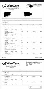
-To run the aux wires I wanted the stock like setup felt like this would be nice so I went to wirecare.com and ordered the connectors.
-Relay box concours specialties has a 6 fuse and 6 relay water tight build. (find on Amazon)
-ObdLinkMX+ (Find on Amazon) you can get the cheaper one I prefer the Bluetooth and wireless
-AlphaOBD to program the truck with the aux switches, okay so they have a windows version and android I bought windows and it sucked went with the android was a lot more user friendly and cheaper. (Google play store)
- Security bypass harness (Zautomotive.com)
-aux switches you can find them in multiple places but keep in mind there are a lot of options like air suspension, exhaust brake, tow haul, parking sensors, etc. so find one that matches up with you like mine I have the diesel the tow haul and exhaust brake are switches around on the one with the aux switches however they function as they should.
Tools needed
-8mm socket
- drill with drill bits
-closed barrel wire crimper
-soldering iron
-heat shrink tubing
-16 awg wire (<5’ runs x 6)
-wiring loom
- torxs bit
First I removed my radio I have the 12” Uconnect myself screws located at the top the. You feel like your about to destroy your truck as the rest is clipped in and you tug and you pull and you freak out because you feel like you just broke something. Take your time it does require you to pull with some force to get it to come out.
Okay once out look where your toggle switches or blank is/are and remove the torx screws and pry the clips and replace with new one and put it all back together we are done here.
At this point I played with alphaOBD finally got it to work on android platform better than the windows and found under instrument panel you can enable the 3-6 aux switches and for me to adjust them it’s not through the radio it’s on my 7” gauge cluster under commercial settings. Default pin is 0000 then you can set them up to run off ignition, or constant battery, momentarily, or latching, and the last state they were on or off.
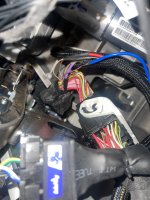
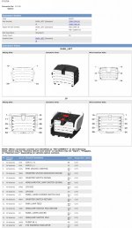
Okay the hard part so once you decide on your relay box weather you want to build the factory harness or go after market under the steering column remove the 2 8mm bolts get the panel out of the way. The harness that I have a pic of you will any to access the little brown wires could CAUTION ⚠️ COULD POTENTIALLY BE DIFFERENT IN YOUR VEHICLE. Okay so this plug you do not want to mess this up it pretty much controls your vehicle I suggest to get a volt meter to verify I just did a simple conductivity test (the sweating in OHMs that beeps) as the aux switches use ground as the relay trigger wire less potential for fire and over loading the switch itself, (pin out description attached in photos) for my self I cut them flush at the plug pins 34 (Aux 3), 36 (aux 5), 37 (aux 1), 38 (aux 2), 40 (aux 4), and 41 (aux 6) now keep in mind I did verify each one of these with a meter to ensure the were the right ones before cutting them. They will be all brown wires with green, purple, black, white, grey stripes and one tan colored one was aux 5 I believe. So I cut these bad boys and then I stripped the wires soldering the ends and then I drilled a hole through the plastic circle to the left of the brake pedal on the fire wall. And I feed my six color wires out I bought the 16 gauge and 12 gauge wires to match so I could color code my aux switches. I solder them to get her and heat shrink the connections. While your down here you can access the BCM (body control module) and add in you security bypass harness if you haven’t already done so yet.
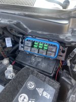
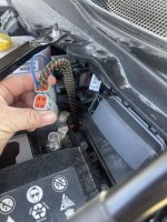
Under the hood
Okay your wiring up your relays if you bought the one like mine you will have to cut and separate the ground wires as these will now become your trigger wire them up with the ones you ran through the fire wall from the aux switches the trigger wires that are the smaller wire will now tie together and be come positive with your accessory positive lead connect to battery and for your power to accessories the stuff you got like me you will crimp your wire to the corresponding connectors.
Okay first can you buy aux switches plug and play no if your vehicle did not come with it then it’s not wired for it.
Second make a plan I will share mine with you and I’m not saying this is right for everyone or you have to get this but this is just simply what I went with. This is why there are options out there and choices but the choice is yours to make on how you want to execute your plan.
Okay so I started off as you might have searching google and finding very little info or knowledge luckily I stumbled onto this post and it gave me the drive to execute this as I wander the stock factory feeling of the aux switches.
Third I will attach pictures of my invoices and the tools needed for extra guidance.
Okay supplies.
-To run the aux wires I wanted the stock like setup felt like this would be nice so I went to wirecare.com and ordered the connectors.
-Relay box concours specialties has a 6 fuse and 6 relay water tight build. (find on Amazon)
-ObdLinkMX+ (Find on Amazon) you can get the cheaper one I prefer the Bluetooth and wireless
-AlphaOBD to program the truck with the aux switches, okay so they have a windows version and android I bought windows and it sucked went with the android was a lot more user friendly and cheaper. (Google play store)
- Security bypass harness (Zautomotive.com)
-aux switches you can find them in multiple places but keep in mind there are a lot of options like air suspension, exhaust brake, tow haul, parking sensors, etc. so find one that matches up with you like mine I have the diesel the tow haul and exhaust brake are switches around on the one with the aux switches however they function as they should.
Tools needed
-8mm socket
- drill with drill bits
-closed barrel wire crimper
-soldering iron
-heat shrink tubing
-16 awg wire (<5’ runs x 6)
-wiring loom
- torxs bit
First I removed my radio I have the 12” Uconnect myself screws located at the top the. You feel like your about to destroy your truck as the rest is clipped in and you tug and you pull and you freak out because you feel like you just broke something. Take your time it does require you to pull with some force to get it to come out.
Okay once out look where your toggle switches or blank is/are and remove the torx screws and pry the clips and replace with new one and put it all back together we are done here.
At this point I played with alphaOBD finally got it to work on android platform better than the windows and found under instrument panel you can enable the 3-6 aux switches and for me to adjust them it’s not through the radio it’s on my 7” gauge cluster under commercial settings. Default pin is 0000 then you can set them up to run off ignition, or constant battery, momentarily, or latching, and the last state they were on or off.
Okay the hard part so once you decide on your relay box weather you want to build the factory harness or go after market under the steering column remove the 2 8mm bolts get the panel out of the way. The harness that I have a pic of you will any to access the little brown wires could CAUTION ⚠️ COULD POTENTIALLY BE DIFFERENT IN YOUR VEHICLE. Okay so this plug you do not want to mess this up it pretty much controls your vehicle I suggest to get a volt meter to verify I just did a simple conductivity test (the sweating in OHMs that beeps) as the aux switches use ground as the relay trigger wire less potential for fire and over loading the switch itself, (pin out description attached in photos) for my self I cut them flush at the plug pins 34 (Aux 3), 36 (aux 5), 37 (aux 1), 38 (aux 2), 40 (aux 4), and 41 (aux 6) now keep in mind I did verify each one of these with a meter to ensure the were the right ones before cutting them. They will be all brown wires with green, purple, black, white, grey stripes and one tan colored one was aux 5 I believe. So I cut these bad boys and then I stripped the wires soldering the ends and then I drilled a hole through the plastic circle to the left of the brake pedal on the fire wall. And I feed my six color wires out I bought the 16 gauge and 12 gauge wires to match so I could color code my aux switches. I solder them to get her and heat shrink the connections. While your down here you can access the BCM (body control module) and add in you security bypass harness if you haven’t already done so yet.
Under the hood
Okay your wiring up your relays if you bought the one like mine you will have to cut and separate the ground wires as these will now become your trigger wire them up with the ones you ran through the fire wall from the aux switches the trigger wires that are the smaller wire will now tie together and be come positive with your accessory positive lead connect to battery and for your power to accessories the stuff you got like me you will crimp your wire to the corresponding connectors.
Attachments
-
 8DEED997-D16D-4777-9BA8-4BDEB29B7813.jpeg209.3 KB · Views: 104
 -
 A4AEAA62-5D67-4C66-AF5A-9E1221BC5565.jpeg417.4 KB · Views: 116
 -
 B6C2E080-78FD-40D4-9AED-3F34B44EF4C2.jpeg510.1 KB · Views: 115
 -
 18416B45-8307-498E-928B-6A61C05DABD4.jpeg529.3 KB · Views: 113
 -
 719FFC8C-68F8-4930-A61C-BEC5A0F31B94.jpeg244.9 KB · Views: 100
 -
 0862A9FB-086B-4264-AF7A-B1C01180C60A.jpeg253.2 KB · Views: 102
rw4363
Active Member
Noticed this when I was browsing today:
Marvelousdude
New Member
- Joined
- Dec 30, 2021
- Messages
- 6
- Reaction score
- 0
Question: What side of the connector did you blunt cut the wires? Male pin side or female pin side of the XY125 connector?Okay the hard part so once you decide on your relay box weather you want to build the factory harness or go after market under the steering column remove the 2 8mm bolts get the panel out of the way. The harness that I have a pic of you will any to access the little brown wires could CAUTION ⚠️ COULD POTENTIALLY BE DIFFERENT IN YOUR VEHICLE. Okay so this plug you do not want to mess this up it pretty much controls your vehicle I suggest to get a volt meter to verify I just did a simple conductivity test (the sweating in OHMs that beeps) as the aux switches use ground as the relay trigger wire less potential for fire and over loading the switch itself, (pin out description attached in photos) for my self I cut them flush at the plug pins 34 (Aux 3), 36 (aux 5), 37 (aux 1), 38 (aux 2), 40 (aux 4), and 41 (aux 6) now keep in mind I did verify each one of these with a meter to ensure the were the right ones before cutting them. They will be all brown wires with green, purple, black, white, grey stripes and one tan colored one was aux 5 I believe. So I cut these bad boys and then I stripped the wires soldering the ends and then I drilled a hole through the plastic circle to the left of the brake pedal on the fire wall. And I feed my six color wires out I bought the 16 gauge and 12 gauge wires to match so I could color code my aux switches. I solder them to get her and heat shrink the connections. While your down here you can access the BCM (body control module) and add in you security bypass harness if you haven’t already done so yet.
I am asking because I was told by Jimmy07 that my AUX wiring is there too . I am thinking of just adding wires on the side without wires and pinning it in the empty cavities.
Noticed this when I was browsing today:View attachment 34252
Where did you see that? Link?
The part number also brings up 82216449aa Aux switch kit for 1500.
Lots of search hits, but no actual parts once you hit the sites.
Users who are viewing this thread
Total: 1 (members: 0, guests: 1)