Ram Heavy Duty Forum

Register a free account today to become a member! Once signed in, you'll be able to participate on this site by adding your own topics and posts, as well as connect with other members through your own private inbox!

Adding the VSIM

Jimmy07

Re-coding from an easy-chair
Joined
Apr 5, 2020
Messages
2,785
Reaction score
3,654
Can anyone enlighten with the definition of the VSIM LSD & HSD signal outputs, The differences between them. I understand the brown cable wires when grounded.
If I choose to use the LSD / HSD outputs as a trigger on a relay, should the relay have a resister?

Thanks
HSD= high side driver- it switches battery power on and off.
LSD= low side driver- it switches ground on and off.
 

Nmerc

New Member
Joined
Nov 17, 2022
Messages
2
Reaction score
0
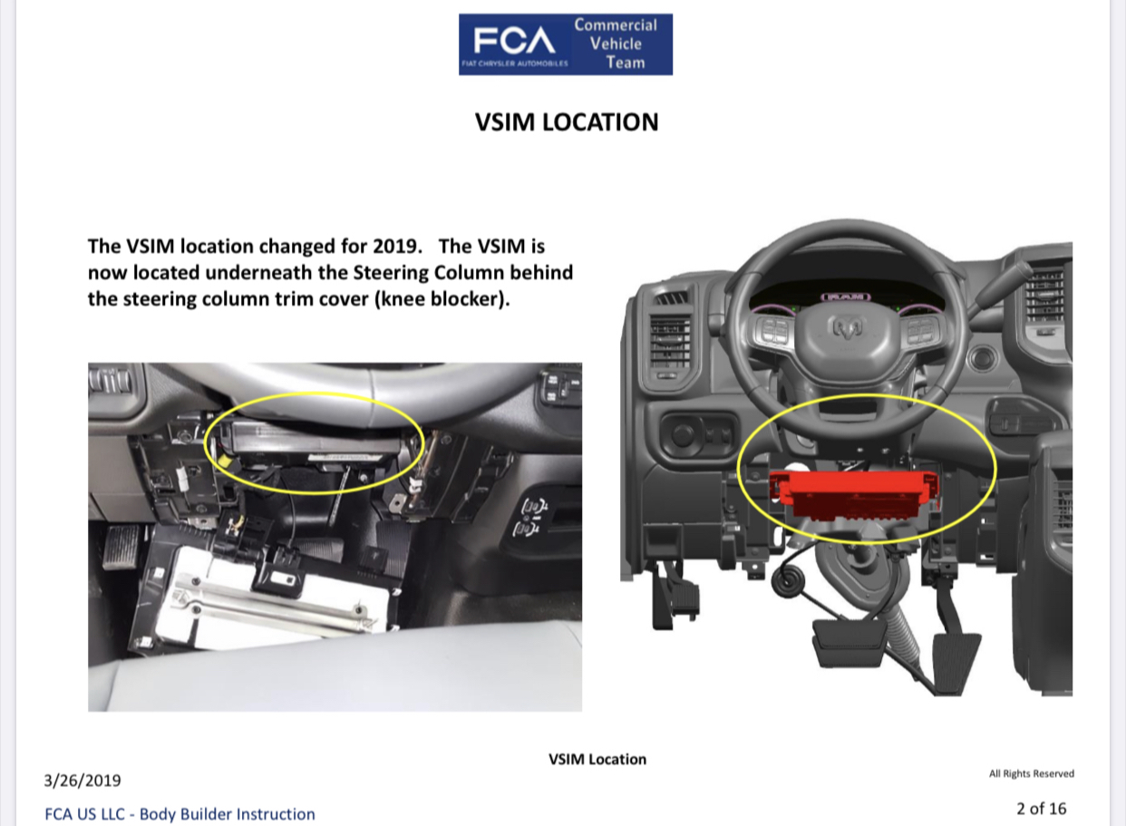
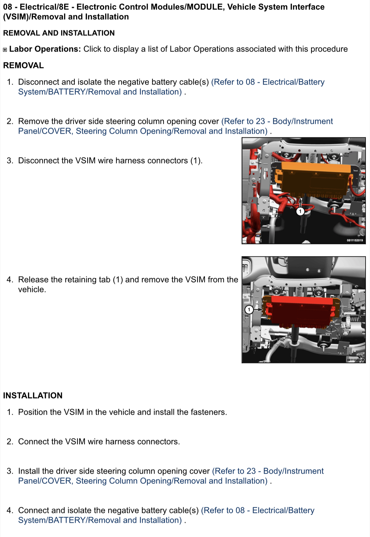
Once the harness is built, mount the VSIM under the steering column.

Etlm05h.jpg


7rZVgQD.jpg


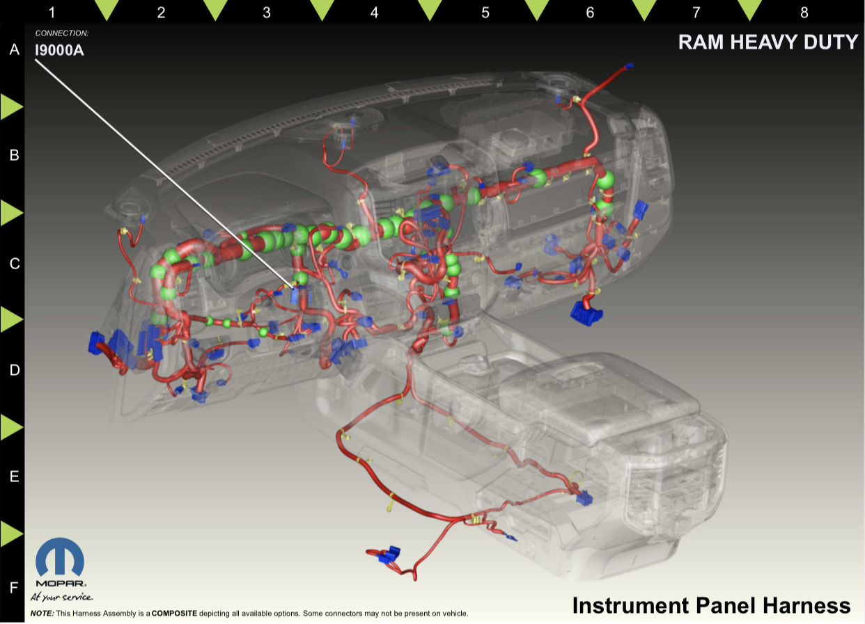
Plug the C1 & C5 connectors of the built harness into the appropriate spots on the VSIM. Route the I9000A connector on the new harness and secure it in this location-

N9tzed3.jpg


gPUV2HH.jpg


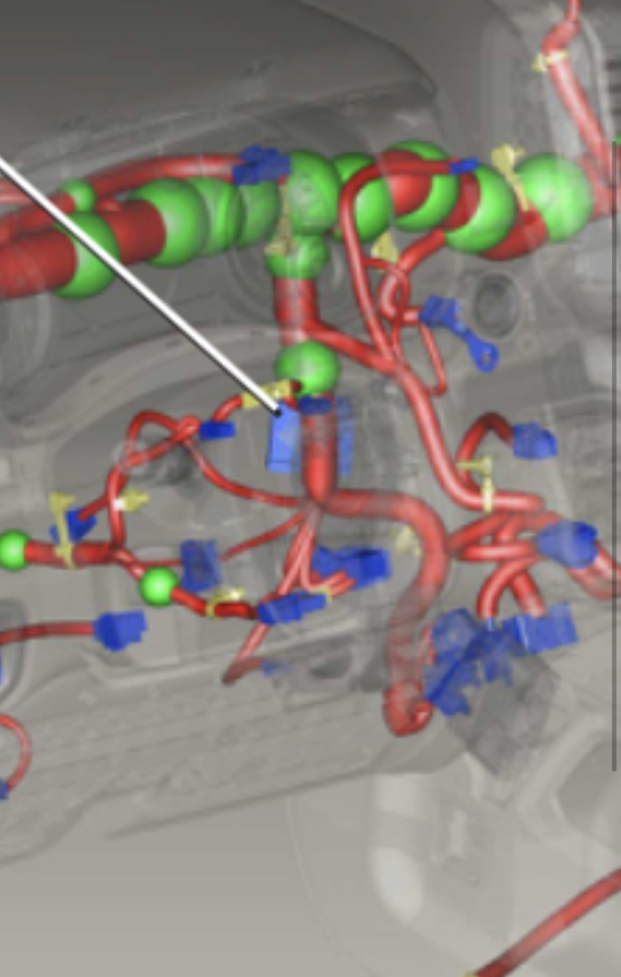
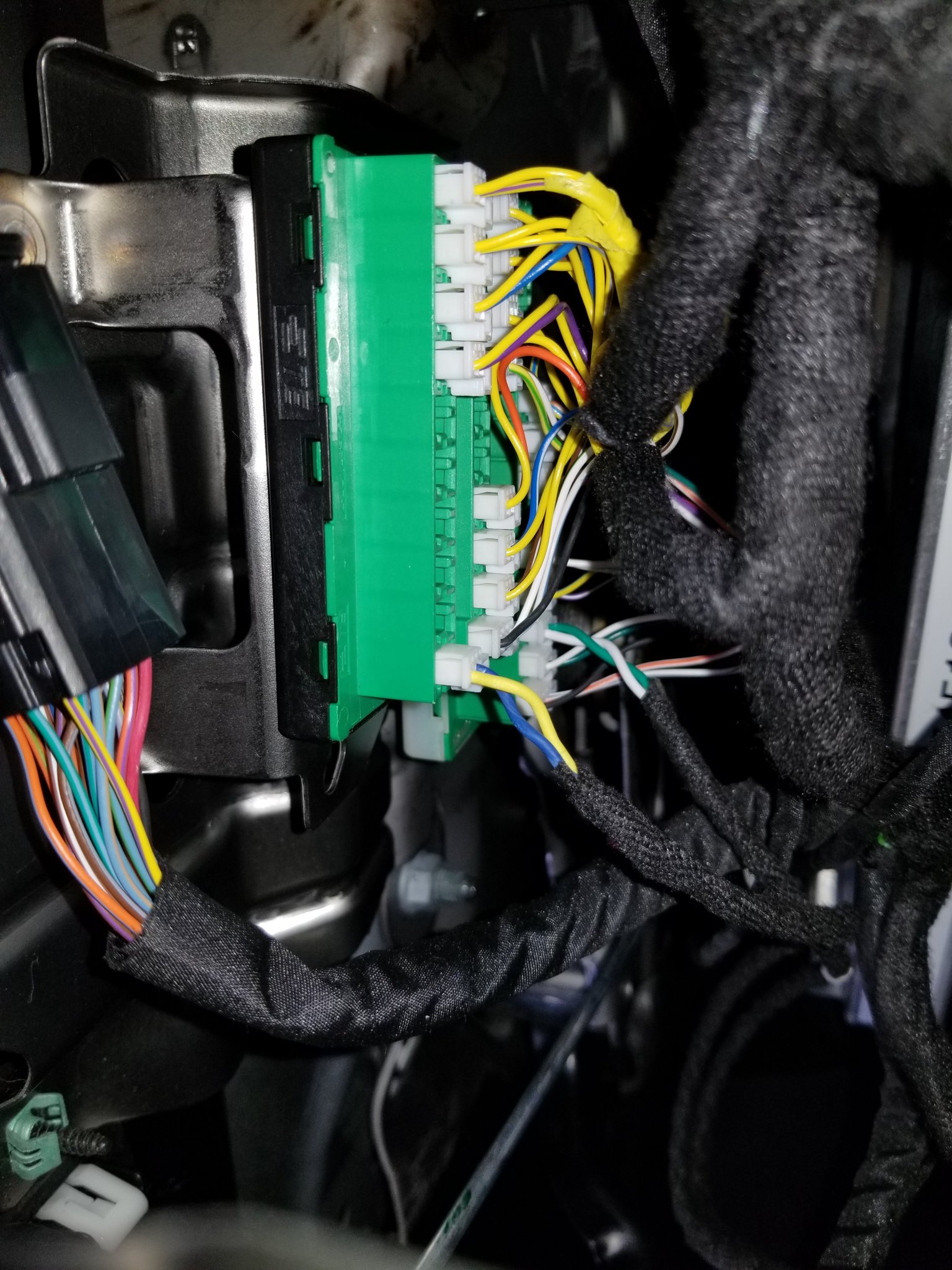
Plug the white canbus c connector into the junction block behind the headlight switch. There are two junction blocks, so you’ll plug into the one with the black base (the one that has yellow wires in each of the connectors plugged into the block).

6cOdODa.jpg


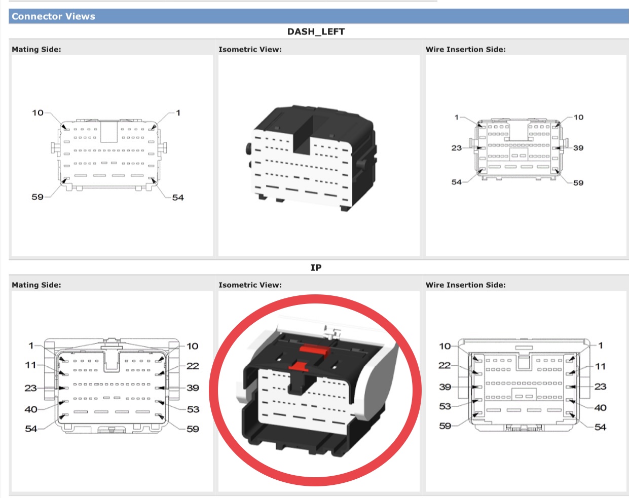
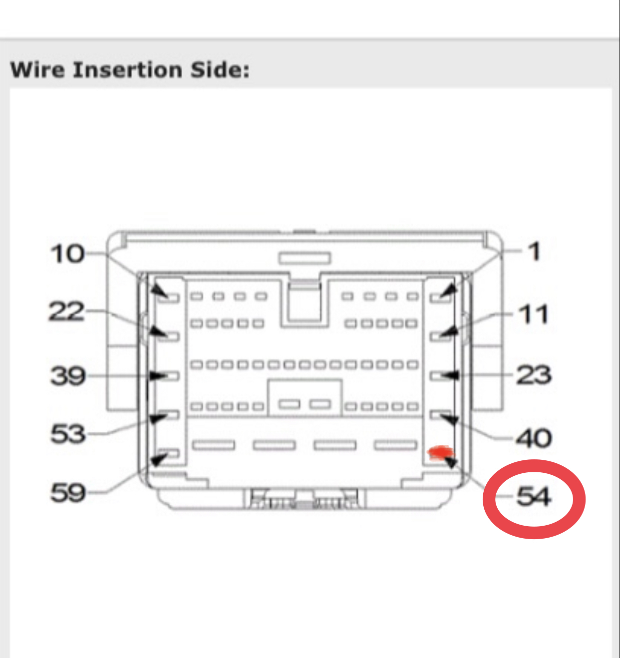
If the red power wire is present in the female XY125A connector half, insert the new harness power wire male terminal into position 54 of the male half of the connector with the lever.

c6jGOMW.jpg


dFvQrIC.jpg


In order to insert that pin all the way into the connector, you have to unlock all the terminals by prying out the face of the connector shown below-

ngFEeGl.jpg


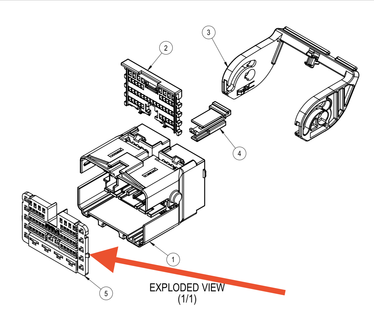
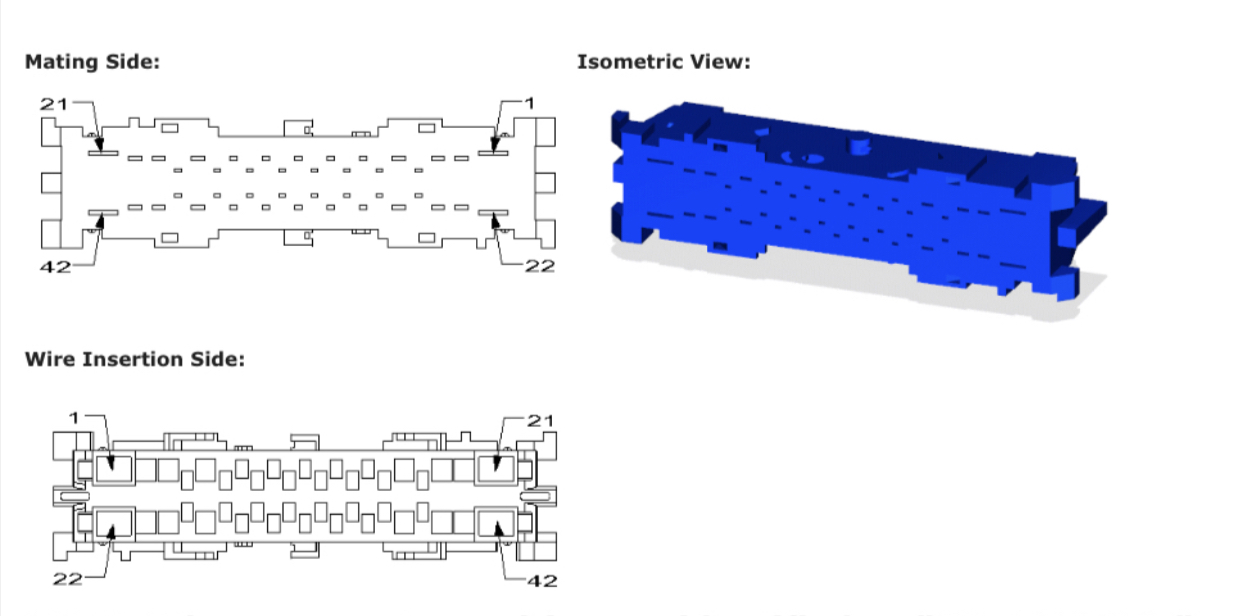
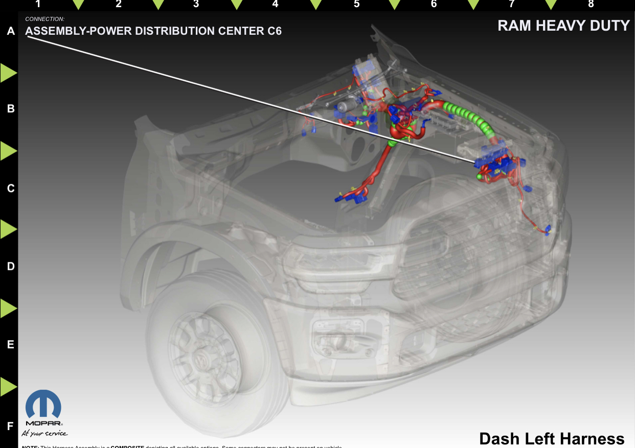
If the red wire is not present in XY125A, then run the harness power wire through the firewall to the PDC. Unclip the PDC and pull it up the gain access to the C6 connector on the bottom, and unplug it. It is the light gray connector-

Lwyu5gU.jpg
scI6XPA.jpg


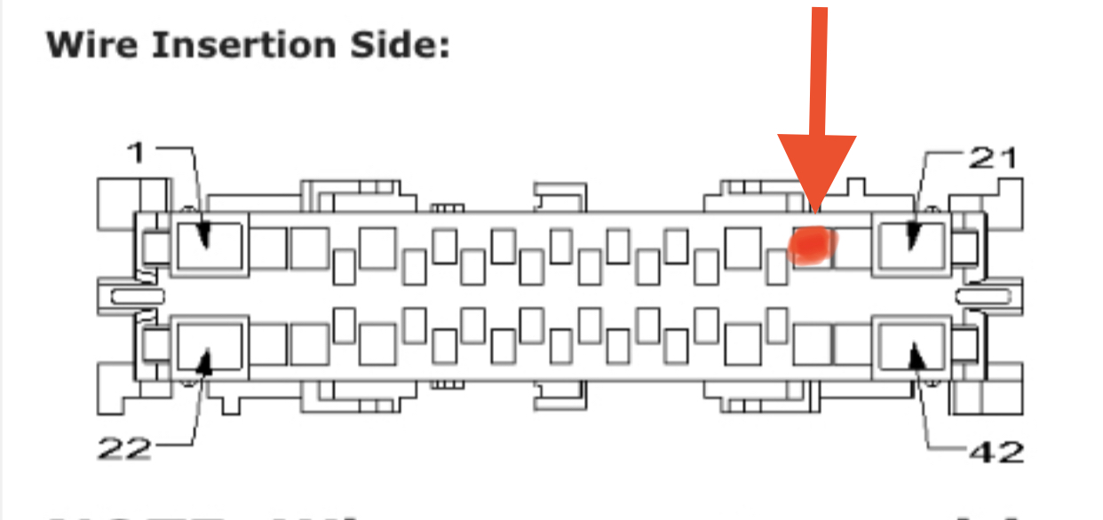
Insert the wire into position 19. Same thing as before, pry the face of the connector out to insert the terminal all the way.

O5QxNlq.jpg


Same thing as before, pry the face of the connector out to insert the terminal all the way.

Run the ground wire to the drive side footwell, and bolt the ring terminal to one of the factory ground bolts in that area.

Use AlfaOBD to enable P/T Cassis Net: VSIM Vehicle System Interface.
Do you happen to know the part number for that junction block with the black base?
 

Mlschrage

New Member
Joined
Jul 17, 2023
Messages
19
Reaction score
1
I need some help. I have a 23 laramie i want to put a v sim in. It doesnt have the i9000a connector nore the right main gray ( my existing connector is a different style) connector or the blue. Does anybody have a pin out for the main gray connector that plugs into the vsim and the blue connector
 

Midwesterner

Active Member
Joined
Jun 13, 2023
Messages
52
Reaction score
143
Location
Nebraska
Would someone be so kind as to post a picture of where the module brackets bolt up under the knee blocker? There is nothing that jumps out at me that they would bolt up to on a '22 2500. TIA.
 

mountainears

Well-Known Member
Joined
Mar 29, 2022
Messages
590
Reaction score
440
From what I recall it just has some plastic tabs that I broke at least one of the first time I accessed it. Now I have a kind of loose zip tie under the dash that keeps it from falling down when I remove the kick panel :)


Sent from my iPhone using Tapatalk
 

Midwesterner

Active Member
Joined
Jun 13, 2023
Messages
52
Reaction score
143
Location
Nebraska
That might be the simplest option. I'm pretty sure my pickup is missing some captive nuts that the brackets bolt up to.
 

Mlschrage

New Member
Joined
Jul 17, 2023
Messages
19
Reaction score
1
Alright @Jimmy07, here’s that thread asking for details. I want to add the VSIM to my truck and I hear it shouldn’t be too difficult...
Hey I'm wondering if you might have an answer to my question here. Ive added added a v sim module to my truck at home only to find out the v sim does not work unless the truck ignition is on acc. Or above. My question is. Can I plug in the can feed that goes into the vsim into the other can block with the black back. Instead of the white colored can block. ( is the black backed block constant live feed instead of the white backed block. Which I'm assuming is switched since the vsim shuts off)
 

jsalbre

Well-Known Member
Joined
Oct 29, 2019
Messages
2,578
Reaction score
3,292
Location
ID
Hey I'm wondering if you might have an answer to my question here. Ive added added a v sim module to my truck at home only to find out the v sim does not work unless the truck ignition is on acc. Or above. My question is. Can I plug in the can feed that goes into the vsim into the other can block with the black back. Instead of the white colored can block. ( is the black backed block constant live feed instead of the white backed block. Which I'm assuming is switched since the vsim shuts off)

Those blocks have nothing to do with power, they’re the two different CAN busses that the VSIM communicates on.
 

Mlschrage

New Member
Joined
Jul 17, 2023
Messages
19
Reaction score
1
I'll have to confirm but I'm pretty sure the vsim had power and ground feeding it with the ignition off. So the can would have to shut down for the vsim to not work with with ignition off
 

Jimmy07

Re-coding from an easy-chair
Joined
Apr 5, 2020
Messages
2,785
Reaction score
3,654
I'll have to confirm but I'm pretty sure the vsim had power and ground feeding it with the ignition off. So the can would have to shut down for the vsim to not work with with ignition off
The canbus connector from the VSIM has to be plugged into the green canbus junction block with the black base. That is the block behind the headlight switch that is closest the the headlight switch. It’s the one that has all the yellow wires.
 

Mlschrage

New Member
Joined
Jul 17, 2023
Messages
19
Reaction score
1
Here's what I did with my running board lights. Tired in to power and grounds off the vsim to control relays to turn on and off the lights ( ie unlock doors and any door a jar) etc. Now I gotta figure out how to keep the vsim awake without ignition being on.
 

Attachments

  • 20230907_211429.jpg
    20230907_211429.jpg
    604.2 KB · Views: 17

ammdrew

Member
Joined
Aug 15, 2023
Messages
33
Reaction score
42
So anyone find a way to enable blinker cams in the 22's with surround cameras or did ram add a piece of hardware in the 23's?
 

Jimmy07

Re-coding from an easy-chair
Joined
Apr 5, 2020
Messages
2,785
Reaction score
3,654
So anyone find a way to enable blinker cams in the 22's with surround cameras or did ram add a piece of hardware in the 23's?
The 2023 BCM has different firmware to make it happen.
 

Mlschrage

New Member
Joined
Jul 17, 2023
Messages
19
Reaction score
1
Here's what I did with my running board lights. Tired in to power and grounds off the vsim to control relays to turn on and off the lights ( ie unlock doors and any door a jar) etc. Now I gotta figure out how to keep the vsim awake without ignition being on.

The canbus connector from the VSIM has to be plugged into the green canbus junction block with the black base. That is the block behind the headlight switch that is closest the the headlight switch. It’s the one that has all the yellow wires.
So I just confirmed vsim has constant power and the can shuts down. Any one know how I could get the constant can to the vsim not the switched can?
 

Jimmy07

Re-coding from an easy-chair
Joined
Apr 5, 2020
Messages
2,785
Reaction score
3,654
So I just confirmed vsim has constant power and the can shuts down. Any one know how I could get the constant can to the vsim not the switched can?
Canbus has nothing to do with constant or switched power.
The VSIM can only be plugged into the one specific bus block that I mentioned earlier. It will not function on the other bus.
Are you absolutely certain that you are feeding the vsim constant battery power? What are the vsim circuit numbers you are trying to use?
 

Mlschrage

New Member
Joined
Jul 17, 2023
Messages
19
Reaction score
1
Canbus has nothing to do with constant or switched power.
The VSIM can only be plugged into the one specific bus block that I mentioned earlier. It will not function on the other bus.
Are you absolutely certain that you are feeding the vsim constant battery power? What are the vsim circuit numbers you are trying to use?
Yes I'm 100% sure it's fed live power and ground I just tested it. And I unplugged the connector with the can lines on it and had no voltage until I turned ignition on to acc or higher.
 

Jimmy07

Re-coding from an easy-chair
Joined
Apr 5, 2020
Messages
2,785
Reaction score
3,654
Yes I'm 100% sure it's fed live power and ground I just tested it. And I unplugged the connector with the can lines on it and had no voltage until I turned ignition on to acc or higher.
Forget about the canbus lines. If the vsim canbus connector is plugged into the green block with the black base directly behind the headlight switch, that’s all that matters.
What are the VSIM circuit numbers you are trying to use?
 

Mlschrage

New Member
Joined
Jul 17, 2023
Messages
19
Reaction score
1
Yes I'm 100% sure it's fed live power and ground I just tested it. And I unplugged the connector with the can lines on it and had no voltage until I turned ignition on to acc or higher.
Is it possible that since the truck was not programed for the v sim thats why it only works on ignition?
 

Jimmy07

Re-coding from an easy-chair
Joined
Apr 5, 2020
Messages
2,785
Reaction score
3,654
Is it possible that since the truck was not programed for the v sim thats why it only works on ignition?
Did you use AlfaOBD to enable P/T Cassis Net: VSIM Vehicle System Interface?
 

Users who are viewing this thread

Top