
Ram Heavy Duty Forum
You are using an out of date browser. It may not display this or other websites correctly.
You should upgrade or use an alternative browser.
You should upgrade or use an alternative browser.
Adding the VSIM
- Thread starter jsalbre
- Start date
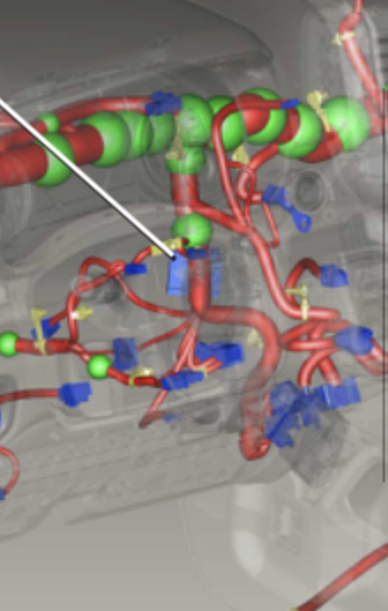
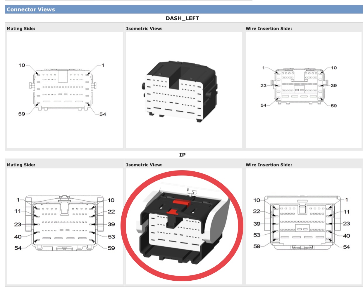
First thing you need to do is see if the power wire for the VSIM is already populated from the PDC (fuse box) to the 59-way connector in the cab at the footwell. This will determine whether or not you have to run the VSIM power wire through the firewall. Look up in the driver side footwell for the 59-way connector (XY125A inline connector)-
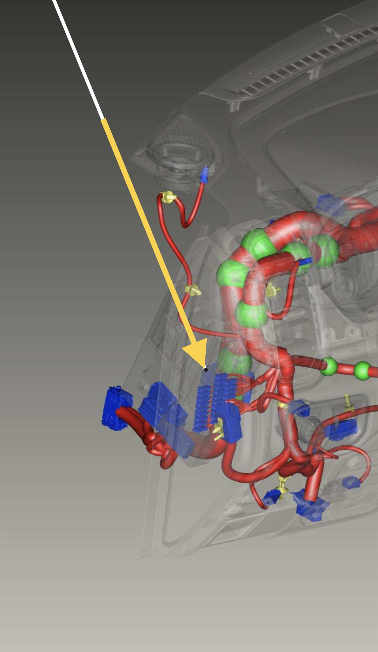
Unplug it, and look at the wires going into the half that has the female terminals (the half without the lever)-
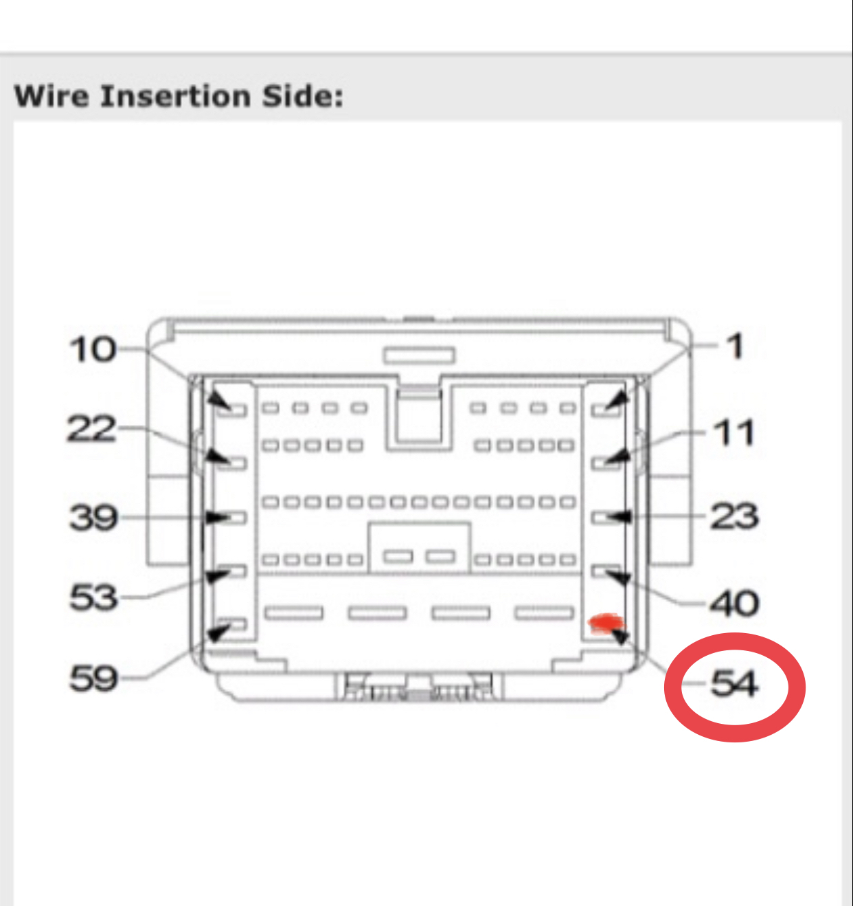
See if there is a red wire in position 54-
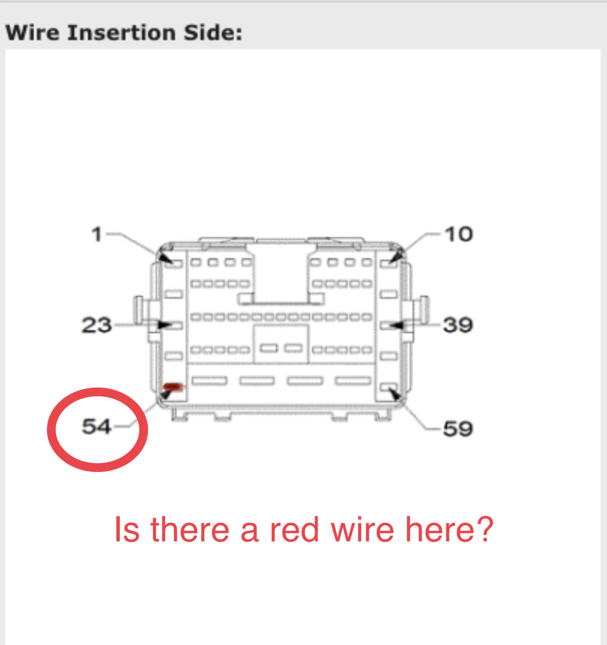
If it’s there, you’re going to build the harness so the VSIM power wire inserts into the male half of that connector with the lever. If it is not there, you’re going to bypass that in-line connector altogether, and go through the firewall straight to the C6 connector, position 19, at the PDC.
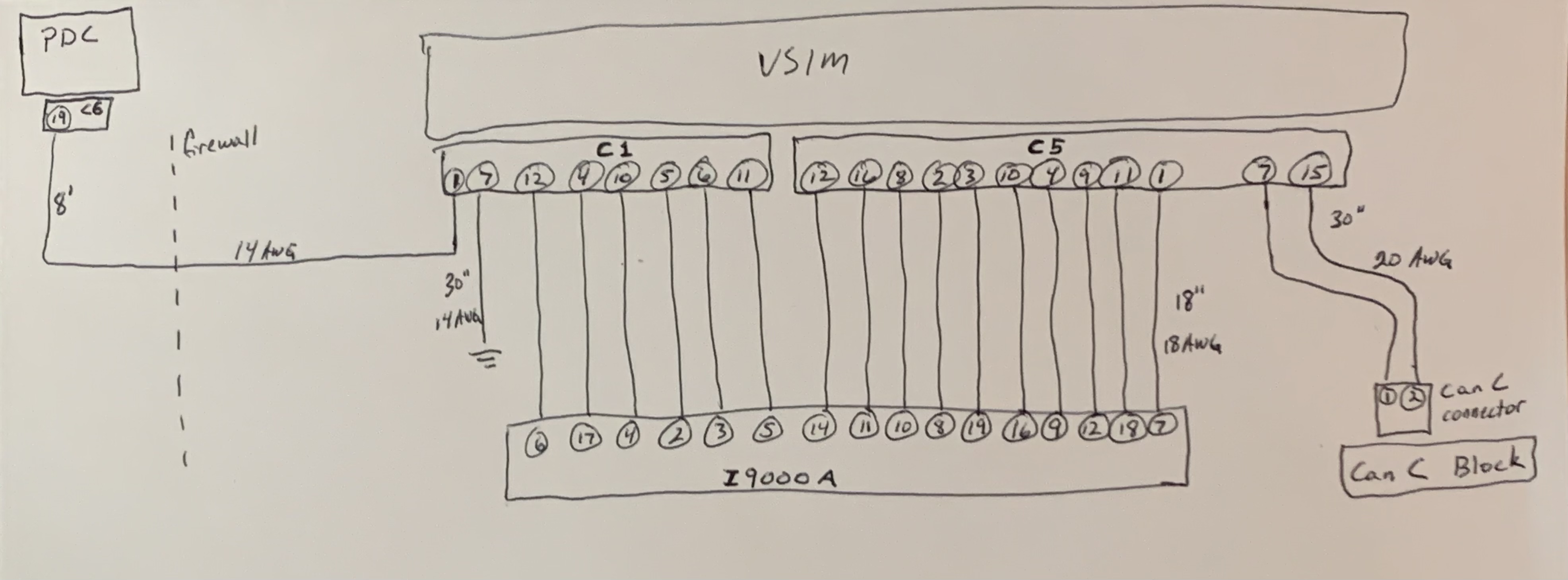
Once this is determined, you can start building the harness. The harness consists of two connectors that plug into the VSIM (referred to as C1 & C5), one inline connector that gets secured by the steering column (I9000A), one canbus C connector that plugs into the can c junction block behind the headlight switch, a power wire, and a ground. Diagram with connector/wire positions-
Unplug it, and look at the wires going into the half that has the female terminals (the half without the lever)-
See if there is a red wire in position 54-
If it’s there, you’re going to build the harness so the VSIM power wire inserts into the male half of that connector with the lever. If it is not there, you’re going to bypass that in-line connector altogether, and go through the firewall straight to the C6 connector, position 19, at the PDC.
Once this is determined, you can start building the harness. The harness consists of two connectors that plug into the VSIM (referred to as C1 & C5), one inline connector that gets secured by the steering column (I9000A), one canbus C connector that plugs into the can c junction block behind the headlight switch, a power wire, and a ground. Diagram with connector/wire positions-
Last edited:
That’s what FCA says about every other option that has been added after the fact.I'm sure it can be done, FCA says no.
*EDIT- Write-up continued*
Parts list:
- Module (1)- 68410361AF
- Left bracket (1)- 68399934AC
- Right bracket (1)- 68399933AC
- Mounting base (1)- 68383601AC
- Screw (4)- 06510245AA
- Wiring bag (1)- 68361228AC
- VSIM C1 connector (1)- Yazaki 7283-6467-40
- C1 terminals- Yazaki 7116-4110-02
- VSIM C5 connector- Yazaki 7283-9080-90
- C5 terminals- Yazaki 7116-4618-02
- I9000A connector- Molex 30968-1247
- I9000A small terminals (12 total) (pin positions 2-7, 14, 16-19)- TE Connectivity 2-1419158-5
- I9000A medium terminals (5 total) (pin positions 8-12)- Molex 33000-0002
- XY125A pin 54 terminal (14awg)- Yazak 7114-4112-02. Only use this terminal if the wire is populated up to the XY125A female connector half.
- PDC C6 pin 19 terminal (14awg)- Yazaki 7116-4272-02. Only use this terminal if the power wire is no present on the XY125A connector.
- CAN C connector- TE Connectivity 2-2138650-1
- CAN C terminals- TE Connectivity 5-963715-1
- 1/4” Ground ring
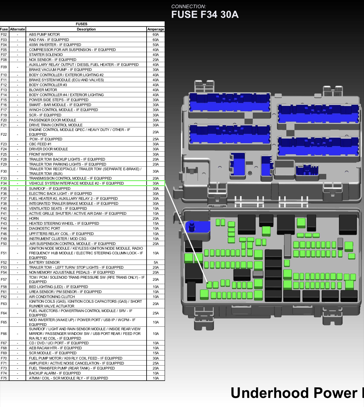
- 30 AMP J-Case fuse (if it is not present in spot F34 in the PDC)-
The Yazaki parts are going to be hard to get, because suppliers only sell them in minimum order quantities, or minimum order price. I get Yazaki parts all the time for other projects, so if needed, I can lump them into one of my orders and build this harness for anyone that needs it.
Last edited:
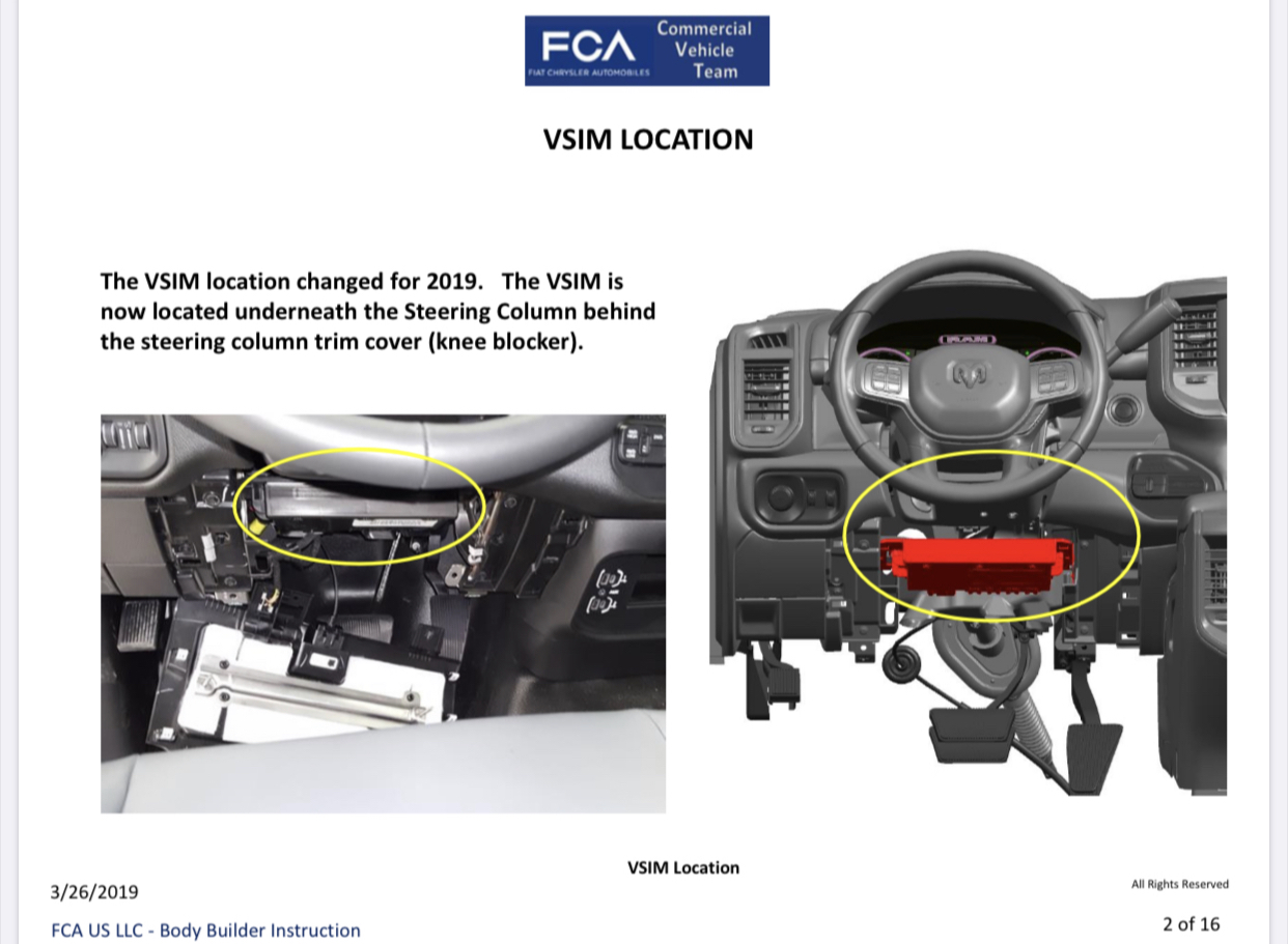
Once the harness is built, mount the VSIM under the steering column.
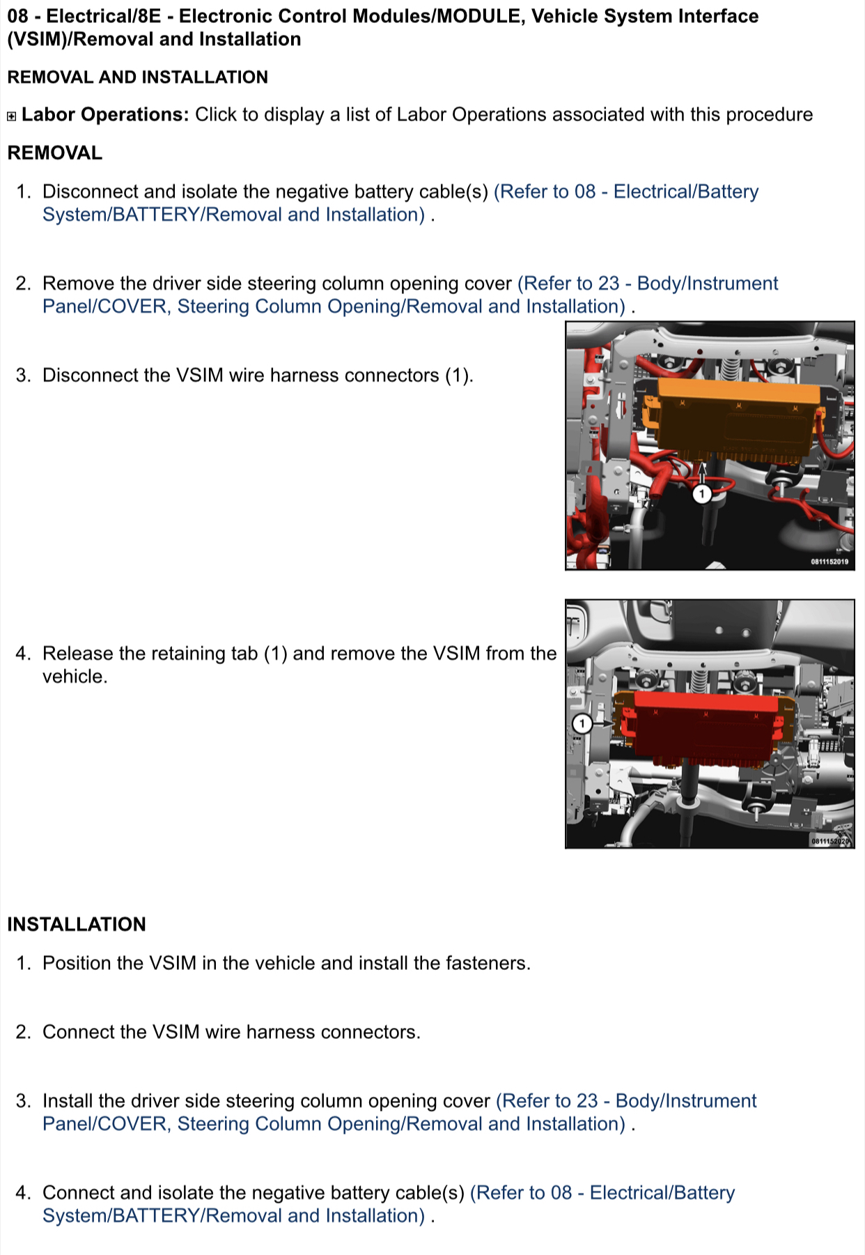
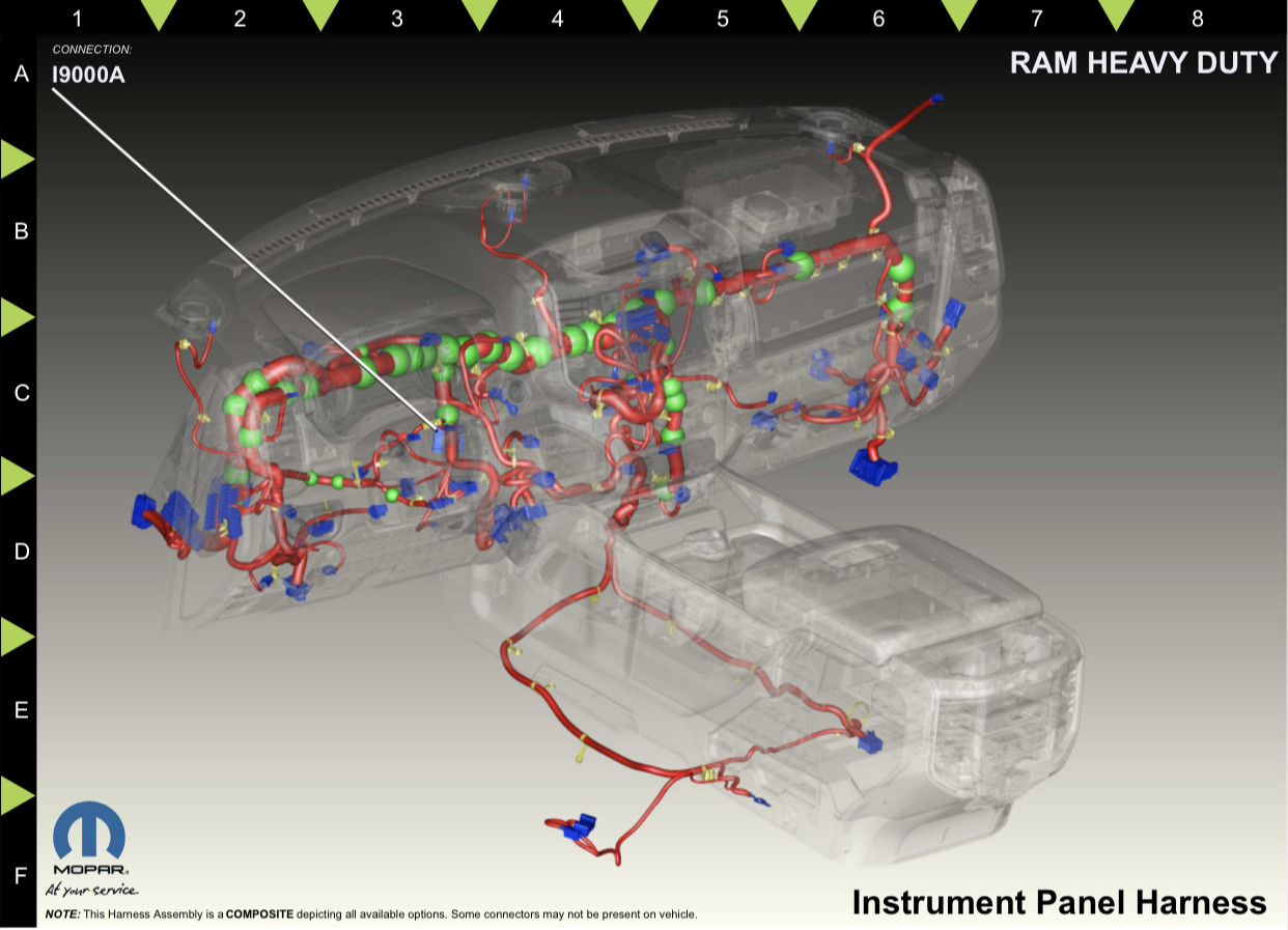
Plug the C1 & C5 connectors of the built harness into the appropriate spots on the VSIM. Route the I9000A connector on the new harness and secure it in this location-
Plug the white canbus c connector into the junction block behind the headlight switch. There are two junction blocks, so you’ll plug into the one with the black base (the one that has yellow wires in each of the connectors plugged into the block).
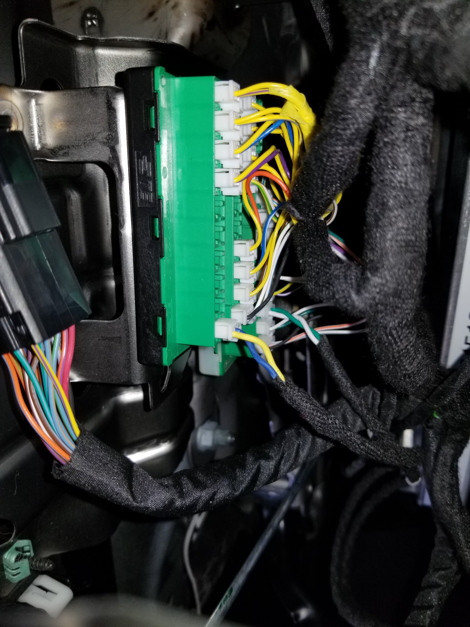
If the red power wire is present in the female XY125A connector half, insert the new harness power wire male terminal into position 54 of the male half of the connector with the lever.
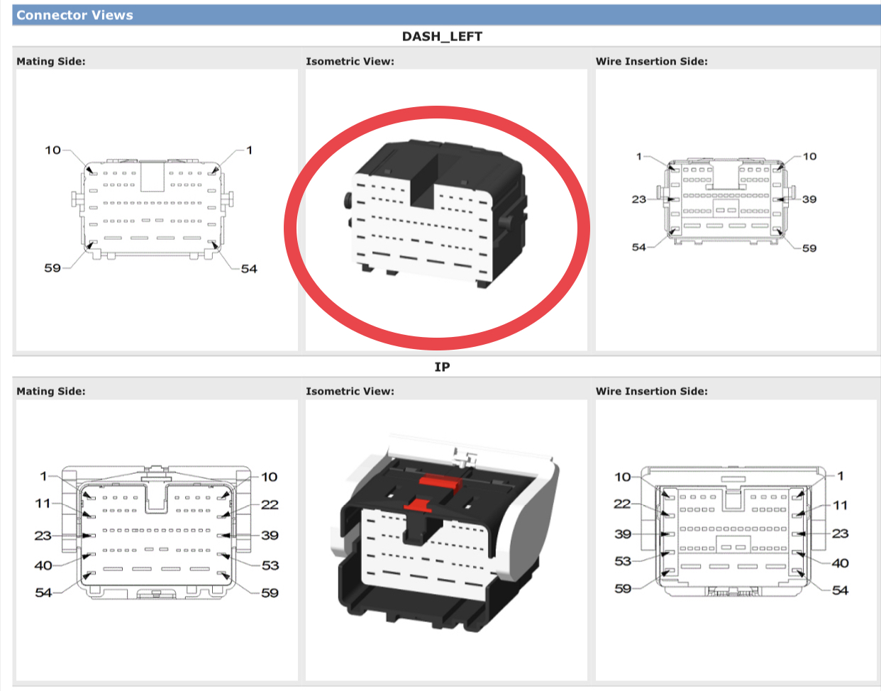
In order to insert that pin all the way into the connector, you have to unlock all the terminals by prying out the face of the connector shown below-
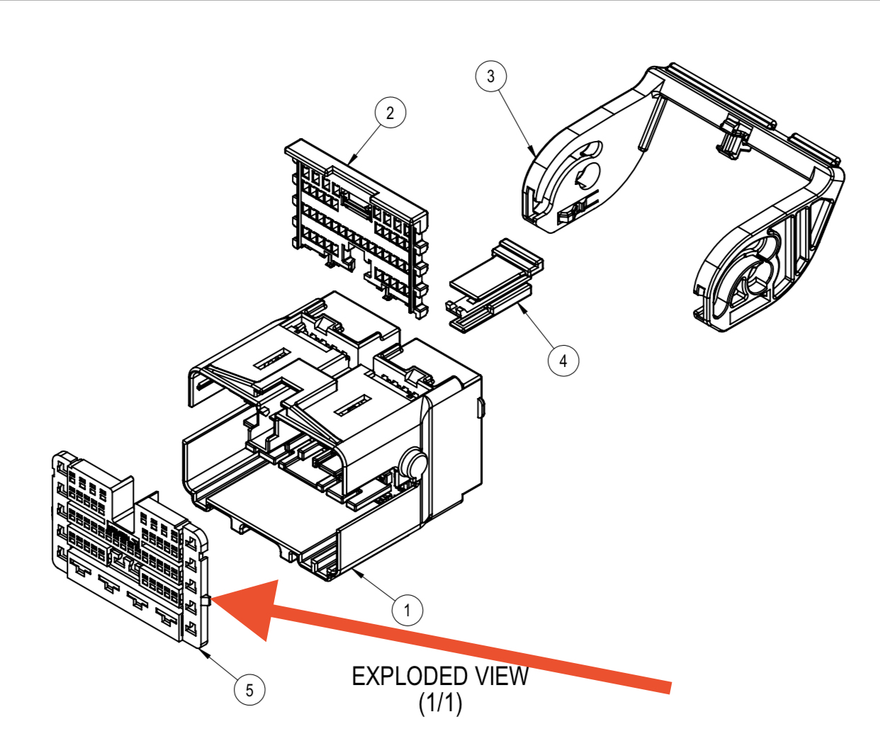
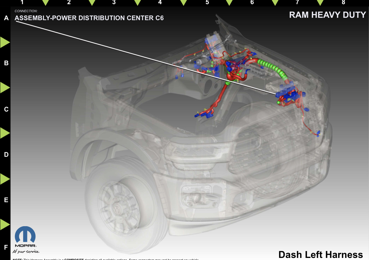
If the red wire is not present in XY125A, then run the harness power wire through the firewall to the PDC. Unclip the PDC and pull it up the gain access to the C6 connector on the bottom, and unplug it. It is the light gray connector-
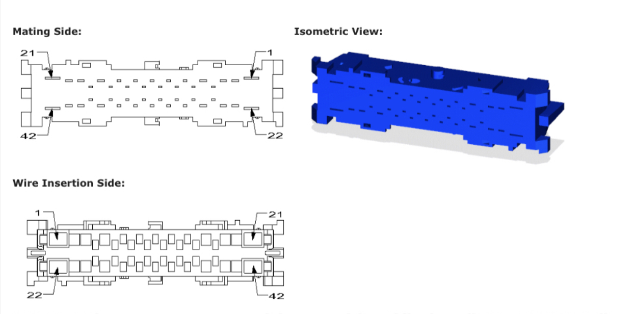
Insert the wire into position 19. Same thing as before, pry the face of the connector out to insert the terminal all the way.
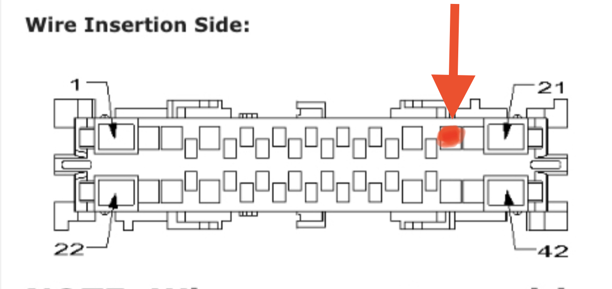
Same thing as before, pry the face of the connector out to insert the terminal all the way.
Run the ground wire to the drive side footwell, and bolt the ring terminal to one of the factory ground bolts in that area.
Use AlfaOBD to enable P/T Cassis Net: VSIM Vehicle System Interface.
Plug the C1 & C5 connectors of the built harness into the appropriate spots on the VSIM. Route the I9000A connector on the new harness and secure it in this location-
Plug the white canbus c connector into the junction block behind the headlight switch. There are two junction blocks, so you’ll plug into the one with the black base (the one that has yellow wires in each of the connectors plugged into the block).
If the red power wire is present in the female XY125A connector half, insert the new harness power wire male terminal into position 54 of the male half of the connector with the lever.
In order to insert that pin all the way into the connector, you have to unlock all the terminals by prying out the face of the connector shown below-
If the red wire is not present in XY125A, then run the harness power wire through the firewall to the PDC. Unclip the PDC and pull it up the gain access to the C6 connector on the bottom, and unplug it. It is the light gray connector-
Insert the wire into position 19. Same thing as before, pry the face of the connector out to insert the terminal all the way.
Same thing as before, pry the face of the connector out to insert the terminal all the way.
Run the ground wire to the drive side footwell, and bolt the ring terminal to one of the factory ground bolts in that area.
Use AlfaOBD to enable P/T Cassis Net: VSIM Vehicle System Interface.
Last edited:
Previous posts edited with info.
VSIM info and wiring:
https://drive.google.com/file/d/1QhLzrcFy0-LD6pu-7WEmDPm3jjlXbzdV/view?usp=drivesdk
Body builder guide document:
https://www.ramtrucks.com/BodyBuild...jGgHzAHGUTU0WB3rWuqSY7YmQ2vEhuBWBA0j5k6/NHai
VSIM info and wiring:
https://drive.google.com/file/d/1QhLzrcFy0-LD6pu-7WEmDPm3jjlXbzdV/view?usp=drivesdk
Body builder guide document:
https://www.ramtrucks.com/BodyBuild...jGgHzAHGUTU0WB3rWuqSY7YmQ2vEhuBWBA0j5k6/NHai
Excellent work, thank you!
Life in an RV doesn’t lend itself to harness building and ordering lots of spare parts, so what would you consider an appropriate price for building out the relevant harness? I’ll have to check on the power wire in pin 54 of course.
Life in an RV doesn’t lend itself to harness building and ordering lots of spare parts, so what would you consider an appropriate price for building out the relevant harness? I’ll have to check on the power wire in pin 54 of course.
Awesome stuff Jimmy.
Thread is stuck.
Let me know if it's OK to tune up the formatting a little, there's text broken up by image placement, etc. that may not be evident on different screen sizes.
Thread is stuck.
Let me know if it's OK to tune up the formatting a little, there's text broken up by image placement, etc. that may not be evident on different screen sizes.
Is that XY125A one that is blocked by a factory amp?
Sure thing. I only use my iPhone for forum viewing, and I’m not near a laptop to be able to see what you are seeing.Awesome stuff Jimmy.
Thread is stuck.
Let me know if it's OK to tune up the formatting a little, there's text broken up by image placement, etc. that may not be evident on different screen sizes.
It is right by the amp, but not blocked by it (as far as having to remove the amp to get to it).Is that XY125A one that is blocked by a factory amp?
I’ll get a quote on parts from SMD, and figure something out. I’ll PM you a price.Excellent work, thank you!
Life in an RV doesn’t lend itself to harness building and ordering lots of spare parts, so what would you consider an appropriate price for building out the relevant harness? I’ll have to check on the power wire in pin 54 of course.
Bluedevilman
Member
- Joined
- May 28, 2021
- Messages
- 61
- Reaction score
- 94
I'm sorry to sound stupid but what's a VSIM and what's it used for?
I had VSIM in my 2020 power wagon. The truck was totaled in a accident a few weeks ago. I took the module and the package of wires out of the truck. My 2022 should be coming in within the month. Do you know if the VSIM will work with a 2022 following your wiring instructions?
pacu44
Active Member
Here is one idea for itI'm sorry to sound stupid but what's a VSIM and what's it used for?
I doubt it. I don’t see those circuits in the list for vsim.I have VSIM equipped, I was going to play with it after Christmas and see what I could get accomplished.
@Jimmy do you think its possible to use VSIM and wiring to stop the fog lights from being operational while turning or using a turn signal?
I ordered the VSIM with my 2020 3500 tradesman, hooked up the harnesses to it and ran through the firewall and there they have sat since. I’d like to tap into circuit 513 to sense the horn switch and use it to drive my air horns. Question I have is are they all supplying a ground signal so I need a relay or does the 513 or any others send voltage?
Sent from my iPhone using Tapatalk
Sent from my iPhone using Tapatalk
I ordered the VSIM with my 2020 3500 tradesman, hooked up the harnesses to it and ran through the firewall and there they have sat since. I’d like to tap into circuit 513 to sense the horn switch and use it to drive my air horns. Question I have is are they all supplying a ground signal so I need a relay or does the 513 or any others send voltage?
Sent from my iPhone using Tapatalk
Answered my own question, W513 will give me 12+ whenever the horn is pressed. Looks like the solenoid draws 2 amps though so yet another relay will be needed.
Sent from my iPhone using Tapatalk
Last edited:
Can anyone enlighten with the definition of the VSIM LSD & HSD signal outputs, The differences between them. I understand the brown cable wires when grounded.
If I choose to use the LSD / HSD outputs as a trigger on a relay, should the relay have a resister?
Thanks
If I choose to use the LSD / HSD outputs as a trigger on a relay, should the relay have a resister?
Thanks
Users who are viewing this thread
Total: 1 (members: 0, guests: 1)