There are quite a few threads about Adding Aux switches and AlfaOBD to our trucks out there. I did hours of reading them and watching numerous videos on it as well as messages back and forth to get this installed on my truck. I wanted to make a DIY for someone else that wants to do it and keep it as factory as possible yet fairly easy to accomplish. Here are the steps from gathering the needed parts , programming the truck.
Updated red jumper wire instruction and part numbers as well as daisy chain instruction This makes the install a lot easier. Thanks to @JustARam22 for pointing out the issues.(10/10/23) I will come back and remove the part numbers no longer needed.
THIS IS BEING DONE ON A 2020 2500 LARAMIE W/6.7L WITHOUT AUX SWITCHES FROM THE FACTORY. PLEASE FOLLOW THIS AT YOUR OWN RISK!!!!
Thank you to:
@Brutal_HO
@Jimmy07
@Harrisons Garage
@Atty
@elephantrider
@BighornHDRam
Hopefully I didn't miss anyone, if I did, please just send me a message and ill add you to the list.
STEP 1: Parts needed (some part numbers may change over time)
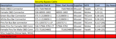
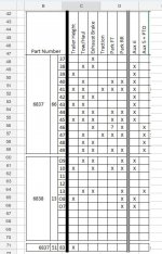
I will attach a spread sheet with parts and cost to this as well.
-Correct switchbank for your particular truck. My part number was: 68376644AE (tow/haul, Exhaust brake, FR/RR park sensors and 6 aux buttons)-$180.
TOOLS:
-Wire diagrams
-Wire Strippers
-Wire Crimpers
-Socket set
-Heat gun
Wiring needed.
-12ga wire red and various color
-14ga wire various color
-20GA 1ft each red,blk and org (i used yellow cause it's what I had available)
-22ga approx 5ft each - 6 different colors
-Wire loom of your choice. I prefer the mesh over the plastic.
-Heat Shrink
-Electrical Tape
Connectors:
-1456989-3 from digikey for jumper harness into back of switchbank
-1419167-1 from TE Connectivity for jumper harness into OE harness
-CID1044-6.3-11 from Connector ID for gray Aux plug on side of AUX PDC
-CID1044-6.3-21 from Connector ID for Female plug on side of AUX PDC
-CID3083 wire seal for gray plug on side of Aux PDC
Terminals:
-CID100-6.3-MS3 from Connector ID for Female side of gray plug (side that won't get used till you add an Acc),
-272-7116414202 from Mouser Electronics for the male side of the gray AUX plug on side of Aux PDC. (plug that wires into AUX PDC)
-63347-1 from Digikey for that goes from Relay switch fuse to 86 terminal of relays
-42475-2 from DigiKey for jumper wire in aux PDC
-180351-2 from Digikey for Jumper Wire in AUX PDC
-571-v23540x7000y21 from Mouser Electronics, pins for plug of jumper harness to back of switch bank
-1438299-4 from Digikey to pin plug that will go to Factory harness from jumper harness.
-Fuses ( i got from amazon)
-871E-1a-d-r1 U19 relays, you will need 5 of them. As of right now they are hard to get. I got them from eBay @$15/2pk
Step 2: Building the Harnesses:
Jumper Harness:
Jumper to OE Harness:
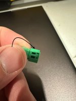
You will need Approx 1ft of Red, Blk and Org 20GA wire along with 3 male pins (pn: 1438299-4) and Black connector (PN: 1419167-1) .
- Put the loom over the wire, tape each end of the look and then Heat shrink it
- Use wire strippers to strip off enough insulation to crimp it to the pin.
-Crimp wire and Pin together ( just an example, I cleaned up the crimp before pinning it)

-Repeat that for the other 2 wires.
Should look like this when done. ( I didn't have ORG wire so i used yellow)

The other end of the wires will go into the connector in the next step.
Jumper harness to back of switch bank:
You will need Approx 5-6ft (maybe less) of 6 different color wire. (I used YW, Beige, WH, Blue, Purple, and orange)., 9 pins PN: 571-v23540x7000y21 and connector 1456989-3
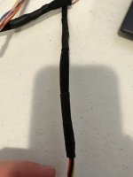
-Put the wire loom over the wires leaving about 2-3in at the connector end and about 6in at the end that will plug into PDC when done. Tape it and Heat shrink it.
-like the other plug you will strip away just enough wire to crimp them to the terminals. Repeat this step 9 times.
-Crimp the terminals to each wire (9 of them)
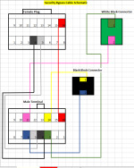
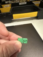
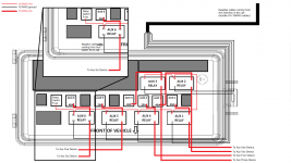
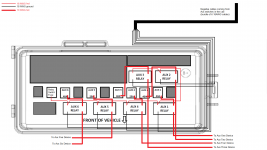
-Insert each pin into the correct location per the diagram. Should look like this when done.

When this step is done you should have the black plug with 3 wires in slot 6,7,8; the other end of those 3 wires should be plugged into the light gray connector in slots 6,7,8. You should have 6 different colored wires coming out of the light gray connector pins 2,3,10,11,12 and 13. The other end of those 6 wires should be blunt cut for now.

Jumper harness from Switch bank to Aux PDC is now done and ready to plug in behind the switch bank.

Jumper Wire in PDC:
For this you will need 6 pieces of 12ga wire (red) cut to approx 4.5" in in length; 6 terminal PN:272-7116414202; 6 terminal CID100-6.3-MS3.
One end of the wire gets the Male terminal, and the other gets the Female Terminal.
Jumper wires should now be done and look like this:

This will end up going from post 30 on the relay to the Fuse. 1 per aux switch
Daisy chain for Relay switch fuse to post 86 on relays:
You will need 7 pices of 18ga wires 1 approx 6in long . The other 6 need to be shorter. approx 2.5" each. Then take the shorter wires and solder them evenly spaced to the longer wire. Also, you will need 6 of the Terminal PN:63347-1 and 1 of the terminal PN:272-7116414202. Before I put the terminals on I mocked the daisy chain up in the PDC to make sure they were the correct length so that they were not too long or too short. Then I crimped the terminals on.
-Strip off just enough wire to crimp the male Terminal to the end of the wire. This is basically what it should look like before you have the Terminals on. The male terminal will go at the end at the top of the pic, the rest will be the gold colored terminals part number: 63347-1.
.jpg")
Will Continue in reply section. Only allows 10 attachments so I cant do it in one long post. I will Add to this once I do the install as well.
Updated red jumper wire instruction and part numbers as well as daisy chain instruction This makes the install a lot easier. Thanks to @JustARam22 for pointing out the issues.(10/10/23) I will come back and remove the part numbers no longer needed.
THIS IS BEING DONE ON A 2020 2500 LARAMIE W/6.7L WITHOUT AUX SWITCHES FROM THE FACTORY. PLEASE FOLLOW THIS AT YOUR OWN RISK!!!!
Thank you to:
@Brutal_HO
@Jimmy07
@Harrisons Garage
@Atty
@elephantrider
@BighornHDRam
Hopefully I didn't miss anyone, if I did, please just send me a message and ill add you to the list.
STEP 1: Parts needed (some part numbers may change over time)
I will attach a spread sheet with parts and cost to this as well.
-Correct switchbank for your particular truck. My part number was: 68376644AE (tow/haul, Exhaust brake, FR/RR park sensors and 6 aux buttons)-$180.
TOOLS:
-Wire diagrams
-Wire Strippers
-Wire Crimpers
-Socket set
-Heat gun
Wiring needed.
-12ga wire red and various color
-14ga wire various color
-20GA 1ft each red,blk and org (i used yellow cause it's what I had available)
-22ga approx 5ft each - 6 different colors
-Wire loom of your choice. I prefer the mesh over the plastic.
-Heat Shrink
-Electrical Tape
Connectors:
-1456989-3 from digikey for jumper harness into back of switchbank
-1419167-1 from TE Connectivity for jumper harness into OE harness
-CID1044-6.3-11 from Connector ID for gray Aux plug on side of AUX PDC
-CID1044-6.3-21 from Connector ID for Female plug on side of AUX PDC
-CID3083 wire seal for gray plug on side of Aux PDC
Terminals:
-CID100-6.3-MS3 from Connector ID for Female side of gray plug (side that won't get used till you add an Acc),
-272-7116414202 from Mouser Electronics for the male side of the gray AUX plug on side of Aux PDC. (plug that wires into AUX PDC)
-63347-1 from Digikey for that goes from Relay switch fuse to 86 terminal of relays
-42475-2 from DigiKey for jumper wire in aux PDC
-180351-2 from Digikey for Jumper Wire in AUX PDC
-571-v23540x7000y21 from Mouser Electronics, pins for plug of jumper harness to back of switch bank
-1438299-4 from Digikey to pin plug that will go to Factory harness from jumper harness.
-Fuses ( i got from amazon)
-871E-1a-d-r1 U19 relays, you will need 5 of them. As of right now they are hard to get. I got them from eBay @$15/2pk
Step 2: Building the Harnesses:
Jumper Harness:
Jumper to OE Harness:
You will need Approx 1ft of Red, Blk and Org 20GA wire along with 3 male pins (pn: 1438299-4) and Black connector (PN: 1419167-1) .
- Put the loom over the wire, tape each end of the look and then Heat shrink it
- Use wire strippers to strip off enough insulation to crimp it to the pin.
-Crimp wire and Pin together ( just an example, I cleaned up the crimp before pinning it)
-Repeat that for the other 2 wires.
Should look like this when done. ( I didn't have ORG wire so i used yellow)
The other end of the wires will go into the connector in the next step.
Jumper harness to back of switch bank:
You will need Approx 5-6ft (maybe less) of 6 different color wire. (I used YW, Beige, WH, Blue, Purple, and orange)., 9 pins PN: 571-v23540x7000y21 and connector 1456989-3
-Put the wire loom over the wires leaving about 2-3in at the connector end and about 6in at the end that will plug into PDC when done. Tape it and Heat shrink it.
-like the other plug you will strip away just enough wire to crimp them to the terminals. Repeat this step 9 times.
-Crimp the terminals to each wire (9 of them)
-Insert each pin into the correct location per the diagram. Should look like this when done.
When this step is done you should have the black plug with 3 wires in slot 6,7,8; the other end of those 3 wires should be plugged into the light gray connector in slots 6,7,8. You should have 6 different colored wires coming out of the light gray connector pins 2,3,10,11,12 and 13. The other end of those 6 wires should be blunt cut for now.
Jumper harness from Switch bank to Aux PDC is now done and ready to plug in behind the switch bank.
Jumper Wire in PDC:
For this you will need 6 pieces of 12ga wire (red) cut to approx 4.5" in in length; 6 terminal PN:272-7116414202; 6 terminal CID100-6.3-MS3.
One end of the wire gets the Male terminal, and the other gets the Female Terminal.
Jumper wires should now be done and look like this:
This will end up going from post 30 on the relay to the Fuse. 1 per aux switch
Daisy chain for Relay switch fuse to post 86 on relays:
You will need 7 pices of 18ga wires 1 approx 6in long . The other 6 need to be shorter. approx 2.5" each. Then take the shorter wires and solder them evenly spaced to the longer wire. Also, you will need 6 of the Terminal PN:63347-1 and 1 of the terminal PN:272-7116414202. Before I put the terminals on I mocked the daisy chain up in the PDC to make sure they were the correct length so that they were not too long or too short. Then I crimped the terminals on.
-Strip off just enough wire to crimp the male Terminal to the end of the wire. This is basically what it should look like before you have the Terminals on. The male terminal will go at the end at the top of the pic, the rest will be the gold colored terminals part number: 63347-1.
Will Continue in reply section. Only allows 10 attachments so I cant do it in one long post. I will Add to this once I do the install as well.
Attachments
Last edited:


.jpg")


.jpg")


.jpg")
.jpg")
.jpg")
.jpg")