
Ram Heavy Duty Forum
You are using an out of date browser. It may not display this or other websites correctly.
You should upgrade or use an alternative browser.
You should upgrade or use an alternative browser.
Dc to dc charging tie into 3500 battery/alternator
- Thread starter MRMcLellan
- Start date
ssichler
Member
- Joined
- Jun 13, 2022
- Messages
- 13
- Reaction score
- 30
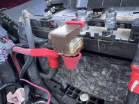
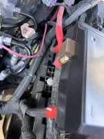
This is how I wired my Renogy DC-DC with MPPT Charger. Positive comes off the main battery post to 80amp circuit breaker. Negative is connected to the battery sensor thingy I think like described in that document (a little hard to follow). 
Installed an onboard charger and wondered where to install the negative lead. l guessed right.
Electronut
Active Member
Good info here guys. I needed this intel as well to wire my Victron 30amp DC to DC charger. I'm going to put positive on the HAPP M5 post and negative on the M6 captured nut or M6 stud of the ground cable on the battery sensor instead of engine block. Should be just as safe and this way truck measure voltages properly through its PCM/BCM.
I guess question I have is should the settings be changed on the Victron for the TV to be in "Smart Charger" or "Standard" conventional charging mode? I would think the earlier due to the IBS tech on the truck. Looking for this item clarification.
I haven't looked at the manual of the truck yet so will take a look there too.
On the post about the charge wire on the 7 pin, if your using a dc to dc charger I'd be safe and remove the positive #4 wire on the 7pin connection and bus bar inside the trailer to not receive any charge off the 7 pin of the truck. Especially if you have lithium batteries installed in the trailer.
Last edited:
Electronut
Active Member
Correct however you also set the minimum voltage charge start parameters and topped off voltage charges of the Victron in conventional charge mode. The Victron also takes the readings for the trailer SOC and auto shuts off charging when they are 100% SOC. So that's why this gets confusing.You want smart. That way it can properly charge your batteries through the various modes. Otherwise it just outputs a constant voltage.
Electronut
Active Member
Actually need to correct my explanation. According to Victron it's identified as "Smart Alternator" setting where voltage always fluctuates. Not sure if that's the same as the built in IBS System.
I would disable. That’s meant for sprinters and other types of European vehicles that have alternators that will reduce output/voltage at certain times.Actually need to correct my explanation. According to Victron it's identified as "Smart Alternator" setting where voltage always fluctuates. Not sure if that's the same as the built in IBS System.
I’d just stick with the default settings and make sure you Orion is seeing those voltages with the truck running. You can take them down .2 or .3 if you need to and I wouldn’t worry. The testing voltage of a lead acid battery will be below 12.5 volts so as long as you don’t set it that low you wouldn’t t have to worry about the Orion charging when the truck is off.
Jeffmc306
Active Member
- Joined
- Apr 7, 2019
- Messages
- 92
- Reaction score
- 157
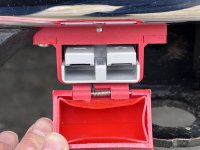
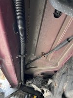
Great information on this thread. I installed a Blue Sea Systems Single MRBF Terminal Fuse Block - 5191 and a 60A fuse for my Renogy 40A DC-DC charger in our Airstream trailer on the 8MM stud. I pulled two 4 ga. welding cable to the bumper and terminated it on an Anderson SB120 connector inside a Trailer Vision housing. I considered using the frame as the ground instead of pulling a dedicated cable but read about voltage drop issues so decided against it.
I pulled an extra smaller gauge wire for the ignition signal wire and connected it to an Aux switch programmed to disconnect when the truck is off.
This was part of a bigger project installing a Battle Born GC3 and Victron MultiPlus II 120x2 50A inverter, charger in the Airstream.
I pulled an extra smaller gauge wire for the ignition signal wire and connected it to an Aux switch programmed to disconnect when the truck is off.
This was part of a bigger project installing a Battle Born GC3 and Victron MultiPlus II 120x2 50A inverter, charger in the Airstream.
Attachments
I have a similar setup, but using the Renogy 60A DCDC. I also put in a 300A continuous duty solenoid that is triggered by ignition on. It’ll get changed over to an Aux switch once I get around to installing those.Great information on this thread. I installed a Blue Sea Systems Single MRBF Terminal Fuse Block - 5191 and a 60A fuse for my Renogy 40A DC-DC charger in our Airstream trailer on the 8MM stud. I pulled two 4 ga. welding cable to the bumper and terminated it on an Anderson SB120 connector inside a Trailer Vision housing. I considered using the frame as the ground instead of pulling a dedicated cable but read about voltage drop issues so decided against it.
I pulled an extra smaller gauge wire for the ignition signal wire and connected it to an Aux switch programmed to disconnect when the truck is off.
This was part of a bigger project installing a Battle Born GC3 and Victron MultiPlus II 120x2 50A inverter, charger in the Airstream.
Additionally I have the charge control on my Renogy hooked to one of the relays on my CerboGX, which turns it on when the voltage from the truck goes above 13v and off when it goes below 12.5V.
My truck has dual alternators so I'm not real concerned with limiting current to 40-60A and will be charging a 600AH lithium bank so I need quite a bit more current. Has anyone just directly connected the truck system to their RV with a solenoid like this guy did with his RV? I figured the current will be limited by wire size/length anyway. I'd like to get around 100-120A charging without having to spend lots of $ on DC-DC chargers (I don't have much room for them anyway with a compact truck-camper).
Jeffmc306
Active Member
- Joined
- Apr 7, 2019
- Messages
- 92
- Reaction score
- 157
Henrys, the problem is lithium batteries have a different charging profile than the AGM / Lead Acid batteries in your truck.My truck has dual alternators so I'm not real concerned with limiting current to 40-60A and will be charging a 600AH lithium bank so I need quite a bit more current. Has anyone just directly connected the truck system to their RV with a solenoid like this guy did with his RV? I figured the current will be limited by wire size/length anyway. I'd like to get around 100-120A charging without having to spend lots of $ on DC-DC chargers (I don't have much room for them anyway with a compact truck-camper).
You need a DC-DC charger that can provide the correct voltage in the bulk/absorption stages and float. For example, Battle Born states you need 14.2-14.6V in bulk/absorption and 13.6V or lower in float.
Protect your investment in that 600A lithium bank with a decent DC-DC charger. Your truck’s dual alternators will be happier too.
I'll second what Jeff said above. You truck batteries direct to your trailer batteries is going to end up with your trailer charging your truck more often than not. If you want a huge amount of power going from the truck to the trailer use more than one DC-DC (I suggest the Renogy, again because they're "affordable" and they work well), and either multiple wire runs or one larger wire run. Also make sure you disconnect your trailer's charge line on the 7-pin when you install a DC-DC charger.My truck has dual alternators so I'm not real concerned with limiting current to 40-60A and will be charging a 600AH lithium bank so I need quite a bit more current. Has anyone just directly connected the truck system to their RV with a solenoid like this guy did with his RV? I figured the current will be limited by wire size/length anyway. I'd like to get around 100-120A charging without having to spend lots of $ on DC-DC chargers (I don't have much room for them anyway with a compact truck-camper).
Why do you need to disconnect your trailer's charge line on the 7-pin when you install a DC-DC charger? I’m getting my parts together to install the Renorgy DC -DC 40 amp to recharge my 2 lead acid batteries. Great thread I have gained some knowledgeI'll second what Jeff said above. You truck batteries direct to your trailer batteries is going to end up with your trailer charging your truck more often than not. If you want a huge amount of power going from the truck to the trailer use more than one DC-DC (I suggest the Renogy, again because they're "affordable" and they work well), and either multiple wire runs or one larger wire run. Also make sure you disconnect your trailer's charge line on the 7-pin when you install a DC-DC charger.
If you don't disconnect it you'll be feeding power back through it to the truck when the DCDC is on, because it'll be putting out higher voltage than the truck is. On an additional note, I recommend not connecting the ground that goes from the DCDC to the truck to anything on the trailer except for the DCDC. If the ground between the DCDC and the truck were to become disconnected and you have the DCDC grounded to the trailer then the electricity would try to follow the little 7pin ground, which would burn up quite quickly.Why do you need to disconnect your trailer's charge line on the 7-pin when you install a DC-DC charger? I’m getting my parts together to install the Renorgy DC -DC 40 amp to recharge my 2 lead acid batteries. Great thread I have gained some knowledge
For your info here's the diagram for my entire system. The DCDC is bottom left to bottom center.

Ahhh! I see what mean. Nice drawing it helps a lot. Thank you for your time.If you don't disconnect it you'll be feeding power back through it to the truck when the DCDC is on, because it'll be putting out higher voltage than the truck is. On an additional note, I recommend not connecting the ground that goes from the DCDC to the truck to anything on the trailer except for the DCDC. If the ground between the DCDC and the truck were to become disconnected and you have the DCDC grounded to the trailer then the electricity would try to follow the little 7pin ground, which would burn up quite quickly.
For your info here's the diagram for my entire system. The DCDC is bottom left to bottom center.
View attachment 55637
Thanks for sharing. I have a very similar setup (minus the DC-DC charger side). My issue is I have a slide-in truck camper with very limited space and DC-DC chargers take up a ton of room and generate a lot of heat. However, I just realized Sterling makes an IP66 rated waterproof 120A DC-DC charger for marine application. I could mount that outside my camper giving me a lot more room to work with.For your info here's the diagram for my entire system. The DCDC is bottom left to bottom center.
carlrx7
Well-Known Member
- Joined
- Oct 20, 2019
- Messages
- 320
- Reaction score
- 286
I went the DC-AC-DC charger route. My RV came with a gen transfer switch but no generator. I installed a 2kw inverter behind the rear seat of the truck (2awg), then ran an extension cord (12 awg) to the back of the truck. The other end of the extension cord went to the transfer switch.. The inverter came with a remote switch that allows me to turn on or off on the fly from the drivers seat. I set multiplus to 10 amp current limit; truck inverter powers the rv and multi charges the batteries up to 1200watts. The 10 amp current limit pulls right at 100 amps of DC from the truck. Dual alts keep the voltage above 13.6. Really helps when low and its raining/no solar coming in on drive days.
Wow interesting. So you're saving some $ on wiring because you can keep the DC side really short and 12V inverters are really cheap.I went the DC-AC-DC charger route. My RV came with a gen transfer switch but no generator. I installed a 2kw inverter behind the rear seat of the truck (2awg), then ran an extension cord (12 awg) to the back of the truck. The other end of the extension cord went to the transfer switch.. The inverter came with a remote switch that allows me to turn on or off on the fly from the drivers seat. I set multiplus to 10 amp current limit; truck inverter powers the rv and multi charges the batteries up to 1200watts. The 10 amp current limit pulls right at 100 amps of DC from the truck. Dual alts keep the voltage above 13.6. Really helps when low and its raining/no solar coming in on drive days.
Jeffmc306
Active Member
- Joined
- Apr 7, 2019
- Messages
- 92
- Reaction score
- 157
Disconnecting the 7 Pin is recommended if you’re charging Lithium batteries due to the higher voltage charging profile. If you’re charging lead acid which are the same as your truck, it’s not a problem.Why do you need to disconnect your trailer's charge line on the 7-pin when you install a DC-DC charger? I’m getting my parts together to install the Renorgy DC -DC 40 amp to recharge my 2 lead acid batteries. Great thread I have gained some knowledge
Just make sure you follow Renogy’s instructions on pg. 18-19 in the manual regarding the DIP switch settings for lead acid and to connect an alternator (ignition) wire to terminal D+ on the DC-DC charger. I plan to use the RAM’s AUX switch set to disconnect when engine is off. This way I can control when the Renogy is engaged and not have to worry about that I forgot to turn it off once we stop.
Interesting way to do it. You're probably losing a bit of efficiency in the back and forth conversion, but I doubt it's much. Plus you have a big inverter in the truck now.I went the DC-AC-DC charger route. My RV came with a gen transfer switch but no generator. I installed a 2kw inverter behind the rear seat of the truck (2awg), then ran an extension cord (12 awg) to the back of the truck. The other end of the extension cord went to the transfer switch.. The inverter came with a remote switch that allows me to turn on or off on the fly from the drivers seat. I set multiplus to 10 amp current limit; truck inverter powers the rv and multi charges the batteries up to 1200watts. The 10 amp current limit pulls right at 100 amps of DC from the truck. Dual alts keep the voltage above 13.6. Really helps when low and its raining/no solar coming in on drive days.
Do you have any pics of your inverter install?
Users who are viewing this thread
Total: 1 (members: 0, guests: 1)