Ram Heavy Duty Forum

Register a free account today to become a member! Once signed in, you'll be able to participate on this site by adding your own topics and posts, as well as connect with other members through your own private inbox!

Dc to dc charging tie into 3500 battery/alternator

MRMcLellan

New Member
Joined
Dec 20, 2021
Messages
2
Reaction score
0
Installing a dc to dc 50 amp charger on my 5th wheel. I am running 4awg wire from truck to dc to dc charger. I am trying to figure out the best place to connect that 4 gauge wire to the battery system. Thoughts ?
 

amauri

Active Member
Joined
Jan 20, 2022
Messages
124
Reaction score
109
And BTW, I am also considering a DC-DC charger installation in our 5th wheel trailer. Having trouble keeping our residential fridge running while towing more than 8 hours at a time.

What model charger did you get?
 

Brutal_HO

The Mad Irishman
Staff member
Joined
Feb 1, 2020
Messages
12,175
Reaction score
21,782
Location
Douglas County, CO
HAPP is tested to 300Amps

Chassis ground to 50A, needs engine ground for higher current draw.

1656797904787.png

Post #7


MRMcLellan

New Member
Joined
Dec 20, 2021
Messages
2
Reaction score
0
Thanks guys -- exactly what I needed. The Renology DC to Dc I am looking at placing in the 5th wheel also is looking for a "smart ignition" feed to it. This is a 50amp converter that will only draw 50 amp if I cut the solar off, otherwise my understanding is that it tops out at about 50% or 25amps. So I hoping my ground can be to frame vs engine. Hoping the "smart ignition" sounds like it is an accurate voltage measurement. Is this ignition feed available via the 7 pin to the trailer or will I need to create a dedicated feed from the truck to the rig?
 

amauri

Active Member
Joined
Jan 20, 2022
Messages
124
Reaction score
109
Some thoughts on the 7-pin trailer connector tow power wire and a DC-DC charger...

I'm also in the process of buying and installing a DC-DC charger for our trailer.
As with most projects, I tend to overthink instead of simply installing something and moving on to the next project. I'm a retired mechanic and have plenty of time to overthink.

What concerns me about simply installing a DC-DC charger per the instructions, is the original 7-pin electrical connection between the trailer and the truck.
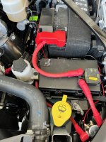
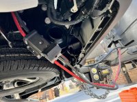
Specifically, the +12v tow wire that connects the truck's battery to the trailer's battery.

Looking at the wiring diagrams, I see that F30 feeds this wire and it goes directly from the fuse box back to the 7-pin connector. There are a couple of connectors in between but it is always live even with ign off.
What is bothering me is that there isn't any diode or similar electrical device that prevents trailer voltage from back feeding to the truck's charging system when the trailer's DC-DC charger is active.

If I install a DC-DC charger in the trailer, I will essentially have two charging systems connected together thru the +12v tow wire on the 7-pin connector.
The truck's charging system will continue to sense and charge the trailer's battery (at a very low amperage) and the trailer's DC-DC charger will also charge the truck's batteries thru the 7-pin connection.

I've been reading about modern alternators that are "smart" and I think I have a basic idea of how it works.
The alternator is controlled by the PCM, bellow is a clip/paste I found describing the Intelligent Battery Sensor.
After reading this, I am wondering if having two charging systems connected together will "confuse" the truck's charging system?

"The IBS serves two primary purposes. The first is to provide the Powertrain Control Module (PCM) with both
immediate and historical calculated battery information, so the PCM can control the charging system. The second
purpose is to provide calculated data to the BCM for operation of the load-shedding feature. A fused power circuit
and the bus are connected to the IBS though a two-terminal connector.
The IBS contains a low value resistor, or shunt. The shunt creates a voltage drop, which is read by an internal
microcontroller to determine the current flow in and out of the battery. In addition to the shunt, the IBS contains a
sensor to monitor the battery’s temperature. Data gathered by the IBS, including temperature, voltage, and current
measurements, are transmitted over a communication bus to the BCM, which is the LIN master node of the IBS. In
addition to real-time measurements, the IBS transmits some calculated battery data over the bus, including SOC and
State of Function (SOF). These values are calculated by storing measurements over time.
SOC = Battery state of charge (or SOC) is expressed as a percentage. The IBS calculates the SOC based on
measured voltage, charge and discharge rates. Therefore, SOC is not a direct percentage of battery voltage.
SOF = Battery State of Function (or SOF) is a calculated prediction of the lowest voltage the battery will drop
to during engine cranking.
The is readable and diagnosable by using the diagnostic scan tool which can display all of the
available parameters needed for vehicle servicing or troubleshooting.
battery sensor
When the IBS is powered up for the first time or is powered after a battery disconnect, it enters a “recalibration”
phase, where the IBS must recognize the type of battery and its characteristics and state. This information is sent to
the IBS by the BCM. In this phase the tolerances on the state functions (SOC, SOF) are greater than in normal
working condition. When the IBS is disconnected from the battery, the device loses its stored memory. When power
is restored, the IBS starts a relearn process. Until the relearn process is complete, accurate battery state information
is unavailable to other vehicle systems. The IBS relearn process requires one start and at least 4 hours with the
vehicle off, electrical system asleep. Remember, the relearn process is restarted every time power is reconnected to
the IBS."
 
Last edited:

Brutal_HO

The Mad Irishman
Staff member
Joined
Feb 1, 2020
Messages
12,175
Reaction score
21,782
Location
Douglas County, CO
Don't these DC-DC chargers have ACR built in?

If not, all you really need to do is work one into the design. I use a BlueSea SI-ACR (120A) for the dual battery (dual engine) setup I installed in my little SeaDoo boat. Works great with two different type batteries - one high CCA start, one house deep cycle. They make them all the way up to 500A.

We just had a member do a high current draw setup on a custom (oil site?) rig and the truck is working fine. that thread can probably be find searching for "HAPP" in the advanced search.


amauri

Active Member
Joined
Jan 20, 2022
Messages
124
Reaction score
109
They do have a an ACR built in, but the 7-pin connector is a separate connection that links both trailer and truck together.

My first thought is to remove the F30 30A fuse that feeds the 7-pin tow wire.
 

ssichler

Member
Joined
Jun 13, 2022
Messages
13
Reaction score
30
Thanks guys -- exactly what I needed. The Renology DC to Dc I am looking at placing in the 5th wheel also is looking for a "smart ignition" feed to it. This is a 50amp converter that will only draw 50 amp if I cut the solar off, otherwise my understanding is that it tops out at about 50% or 25amps. So I hoping my ground can be to frame vs engine. Hoping the "smart ignition" sounds like it is an accurate voltage measurement. Is this ignition feed available via the 7 pin to the trailer or will I need to create a dedicated feed from the truck to the rig?
I bought the same Renogy unit also to connect my 2022 RAM 2500 battery to our new truck camper. Did you get yours installed? Thanks.
 

Vr6mole

Member
Joined
Aug 12, 2020
Messages
55
Reaction score
60
Sharing pics of my install. Ended up running 2/0 to an Anderson plug on the rear of the frame took up up the 35amp 24v sterling DC/DC charger in my travel trailer. The trailer section went down to 4awg. I now have a fifth wheel and will move the anderson up into the bed. Went with 2/0 so I could add an additional DC/DC charger.

Running a 200 amp breaker to a heavy duty solenoid wired up to the factory aux switch.
 

Attachments

  • IMG_5836.jpg
    IMG_5836.jpg
    576.9 KB · Views: 225
  • IMG_5840.jpg
    IMG_5840.jpg
    1 MB · Views: 222

H3LZSN1P3R

You're doing it wrong
Joined
May 29, 2020
Messages
9,182
Reaction score
8,328
Sharing pics of my install. Ended up running 2/0 to an Anderson plug on the rear of the frame took up up the 35amp 24v sterling DC/DC charger in my travel trailer. The trailer section went down to 4awg. I now have a fifth wheel and will move the anderson up into the bed. Went with 2/0 so I could add an additional DC/DC charger.

Running a 200 amp breaker to a heavy duty solenoid wired up to the factory aux switch.
Nice thing about that you can make a set of jumper cables for rear boosting or a utility trailer with a winch, i have everything i need to do the same to mine. just no time
 

john221us

New Member
Joined
Jul 23, 2022
Messages
3
Reaction score
0
Location
California
Sharing pics of my install. Ended up running 2/0 to an Anderson plug on the rear of the frame took up up the 35amp 24v sterling DC/DC charger in my travel trailer. The trailer section went down to 4awg. I now have a fifth wheel and will move the anderson up into the bed. Went with 2/0 so I could add an additional DC/DC charger.

Running a 200 amp breaker to a heavy duty solenoid wired up to the factory aux switch.
I am about to do this. What did you tap into for the accessory power for the solenoid?
 

Ed60

New Member
Joined
Oct 12, 2022
Messages
20
Reaction score
6
Sharing pics of my install. Ended up running 2/0 to an Anderson plug on the rear of the frame took up up the 35amp 24v sterling DC/DC charger in my travel trailer. The trailer section went down to 4awg. I now have a fifth wheel and will move the anderson up into the bed. Went with 2/0 so I could add an additional DC/DC charger.

Running a 200 amp breaker to a heavy duty solenoid wired up to the factory aux switch.
Thanks for sharing. That’s exactly what I have been trying to figure out how to do.

Where do you ground the plug on the truck?
 

Vr6mole

Member
Joined
Aug 12, 2020
Messages
55
Reaction score
60
Thanks for sharing. That’s exactly what I have been trying to figure out how to do.

Where do you ground the plug on the truck?
I grounded to the battery per the instructions of the Sterling DC-DC 12-24 35 amp charger I am using. I honestly am not sure if I needed to. I probably could have just grounded to the rear truck frame but the manual warned of charging not being as efficient.
 

Ed60

New Member
Joined
Oct 12, 2022
Messages
20
Reaction score
6
I grounded to the battery per the instructions of the Sterling DC-DC 12-24 35 amp charger I am using. I honestly am not sure if I needed to. I probably could have just grounded to the rear truck frame but the manual warned of charging not being as efficient.
Thanks again!
 

amauri

Active Member
Joined
Jan 20, 2022
Messages
124
Reaction score
109
If grounding to the battery instead of a ground point on the engine block or chassis, make sure you observe the info detailed in the attached TSB.
The IBS needs to sense battery loads, and any additional load to the system must go thru the IBS.
 

Attachments

  • battery cconnection and charging TBS MC-10173323-9999.pdf
    500.7 KB · Views: 139

Users who are viewing this thread

Top