elephantrider
Hydraulic Lifter Crew
- Joined
- Sep 3, 2019
- Messages
- 2,326
- Reaction score
- 3,020
68376642AE - this is the pn I ordered.
this is what it looks like.

this is what it looks like.
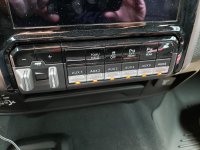
Can you tell me the part number for the switch hereI think I have tracked down the part number for the switch panel I would need. I need to have the tow/haul, traction control, front park sensor and rear park sensor. Just like the image below. Have you tracked down the required terminals and relays?
View attachment 2291
The switch panel part number that I used is 68376640AE.Can you tell me the part number for the switch here
The switch panel part number that I used is 68376640AE.
I did and everything works. It did take some help from Alfaobd to get everything working. To recap I created a plug and play harness that connects right behind the switch panel. I then used an aftermarket fuse/relay panel. I will post the connector part numbers I used, I also have a few extra as I had to order ten each of them.did you get everything wired up?
I did and everything works. It did take some help from Alfaobd to get everything working. To recap I created a plug and play harness that connects right behind the switch panel. I then used an aftermarket fuse/relay panel. I will post the connector part numbers I used, I also have a few extra as I had to order ten each of them.
Thanks for your post and looking forward to that information. This would work nicely on my 2019 Power Wagon for my auxiliary lights!!I did and everything works. It did take some help from Alfaobd to get everything working. To recap I created a plug and play harness that connects right behind the switch panel. I then used an aftermarket fuse/relay panel. I will post the connector part numbers I used, I also have a few extra as I had to order ten each of them.
2019what year is your Ram?
I did and everything works. It did take some help from Alfaobd to get everything working. To recap I created a plug and play harness that connects right behind the switch panel. I then used an aftermarket fuse/relay panel. I will post the connector part numbers I used, I also have a few extra as I had to order ten each of them.
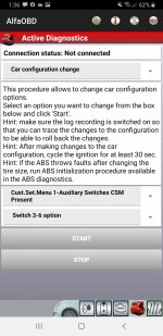
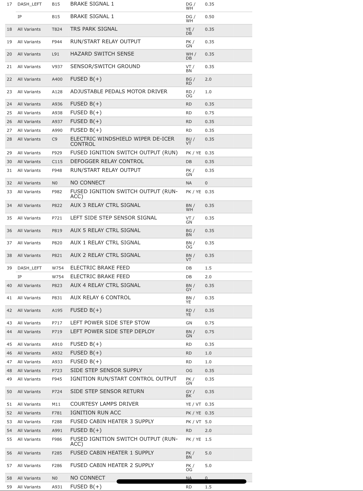
How are you trying to measure the wires that come from the switches? Those aren’t the actual power output wires. All those wires do is complete ground to energize the relay coil in the aux fuse box. So, let’s say all you have installed is the switch bank and the 1-6 switch wires, and you want to see if the number 1 aux switch wire works- you would set your meter to ohms (or continuity buzzer), activate switch 1, probe switch 1’s wire, and put the other probe to metal ground, and you should have continuity.An update for me with installing Aux switches ..I own a 2500 2019 RAM Laramie. In the process of installing the Aux Switches. I have the switches installed and power (I believe) to the switches. By turning on the settings using AlfaOBD shown in my attached pics (first is the "Customer.Set.Menu 1 - Auxiliary Switches CSM" option selected was "Switch 3-6 option") I had the commercial menu become available on the instrument cluster (allows control of permanent power or ignition power etc for all six switches even though the option only says 3-6).
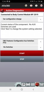
The second pic shows the setting that tells the BCM you have the switches plugged in and then allows them to be turned on and off (with the respective indicator light coming on on the front of the panel). What I can't find though is the output for the Aux switches. I've measured each of the wires and empty terminals on the back of the plug and don't get any change from the readings regardless of the switches being on or off.
Does anyone know if there is a spot/connector anywhere under the dash that provides those outputs for me to use to activate my relay?
Getting so bloody close to getting this sorted and don't want to rip apart anything else just yet..
Thanks in advance. If you have questions about AlfaOBD I am getting more familiar with it all the time, so maybe able to answer some basic questions..
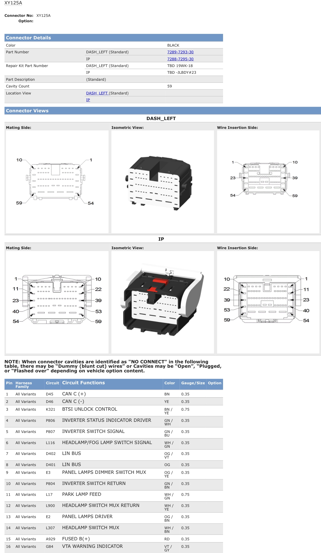
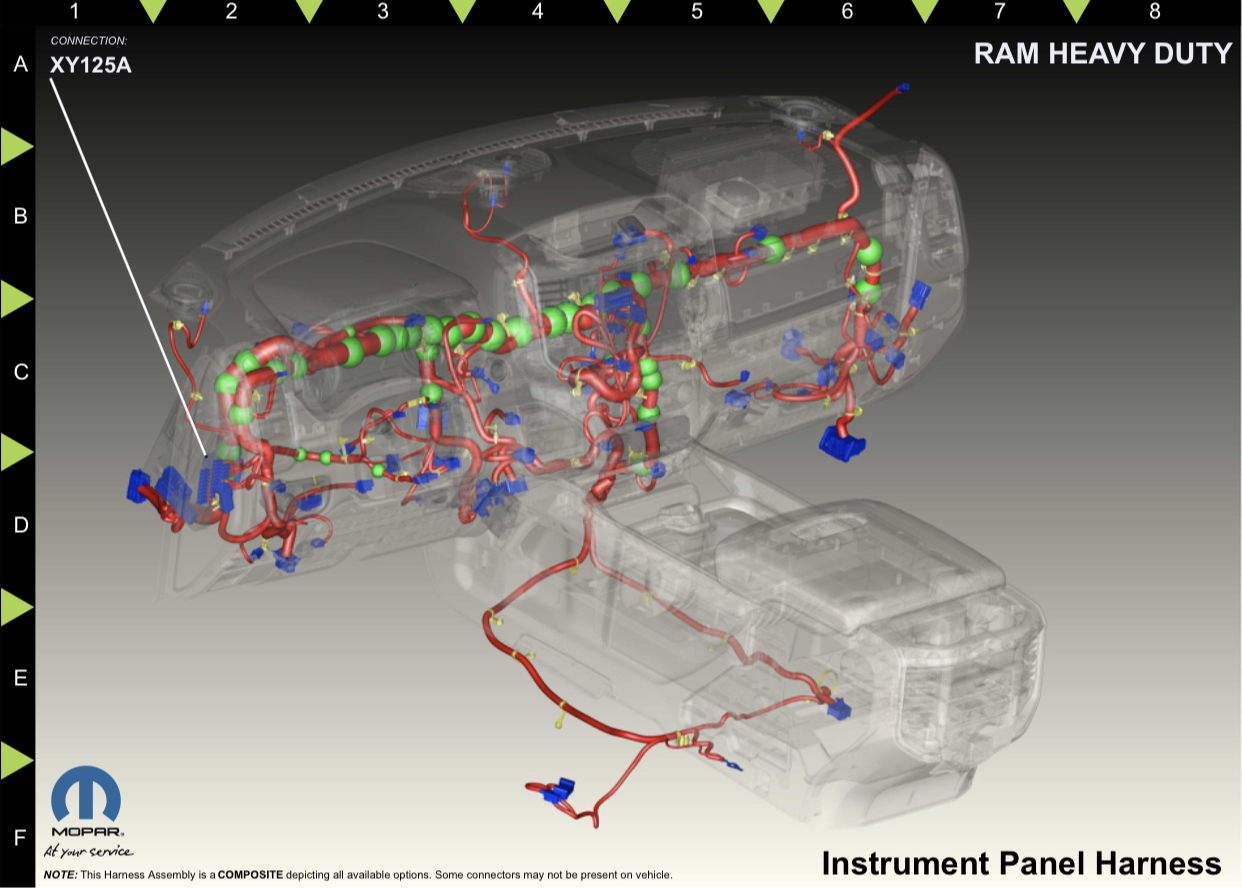
Also, if the six aux switch wires are already populated on the connector that plugs into the switch bank, then their next stop is the xy125 connector at the driver side footwell-An update for me with installing Aux switches ..I own a 2500 2019 RAM Laramie. In the process of installing the Aux Switches. I have the switches installed and power (I believe) to the switches. By turning on the settings using AlfaOBD shown in my attached pics (first is the "Customer.Set.Menu 1 - Auxiliary Switches CSM" option selected was "Switch 3-6 option") I had the commercial menu become available on the instrument cluster (allows control of permanent power or ignition power etc for all six switches even though the option only says 3-6).
The second pic shows the setting that tells the BCM you have the switches plugged in and then allows them to be turned on and off (with the respective indicator light coming on on the front of the panel). What I can't find though is the output for the Aux switches. I've measured each of the wires and empty terminals on the back of the plug and don't get any change from the readings regardless of the switches being on or off.
Does anyone know if there is a spot/connector anywhere under the dash that provides those outputs for me to use to activate my relay?
Getting so bloody close to getting this sorted and don't want to rip apart anything else just yet..
Thanks in advance. If you have questions about AlfaOBD I am getting more familiar with it all the time, so maybe able to answer some basic questions..
Ah, silly me!! Of course they are negative switched. just went and checked and yes they are connected at the switch. Thank you Jimmy07 for your guidance and the images they will help immensely in finding the wires underneath the dash! Which will ultimately save me time and energy.How are you trying to measure the wires that come from the switches? Those aren’t the actual power output wires. All those wires do is complete ground to energize the relay coil in the aux fuse box. So, let’s say all you have installed is the switch bank and the 1-6 switch wires, and you want to see if the number 1 aux switch wire works- you would set your meter to ohms (or continuity buzzer), activate switch 1, probe switch 1’s wire, and put the other probe to metal ground, and you should have continuity.
So the only oem part that can be ordered is the switch bank? I know when I looked into this for my 4th gen the whole kit could be ordered. I’m thinking If this can be done for less than $500 it’s a really clean and nice way to be able to have auxiliary things wired without ugly switches in the cab.Ah, silly me!! Of course they are negative switched. just went and checked and yes they are connected at the switch. Thank you Jimmy07 for your guidance and the images they will help immensely in finding the wires underneath the dash! Which will ultimately save me time and energy.
So the switch ad relay are 2 separate part numbers?I'm hoping to do it for way less than $500.. I have the switch and have relays on the way. Should hopefully have enough wiring and bits and pieces to do the rest.. Or could get a harness from Paulvi and save me some time and effort...