Ram Heavy Duty Forum

Register a free account today to become a member! Once signed in, you'll be able to participate on this site by adding your own topics and posts, as well as connect with other members through your own private inbox!

12 inch UConnect 5 cargo camera in 2022 Ram 2500?

SeanF

New Member
Joined
Sep 15, 2022
Messages
3
Reaction score
0
Hi All,
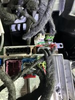
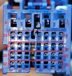
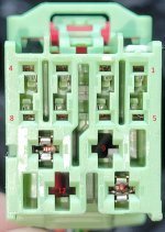
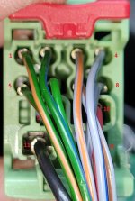
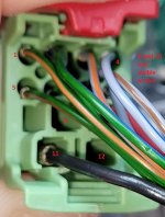
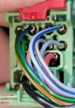
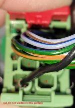
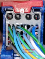
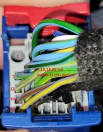
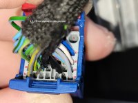
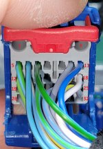
I have been trying to figure out how to connect to the unused cargo camera input on my 2022 Ram 2500 with the 12 inch UConnect system. Everything I have found online refers to a previous generation with a large 52 pin connector on the back of the radio where the cargo camera can be connected to pins 21 and 22. Apparently changed this to multiple connectors for the 2022 model with the 12 inch screen. (See Attached Photo).

Does anybody have a connector pin-out for this newer radio?

More information:
- Truck is a 2022 2500 Laramie with the 6.7 Cummins standard output
- I do not have the surround camera system
- I am going to use this for a front camera.
- I can enable the cargo camera with AlfaOBD
- The camera I have is powered and working
- The camera is a 480P that is using the yellow RCA composite video connector.

Any helpful info would be appreciated!
 

Attachments

  • IMG_8024.JPG
    IMG_8024.JPG
    676 KB · Views: 33

ramreddog

New Member
Joined
Jan 5, 2024
Messages
2
Reaction score
0
Crashing HD with my 2023 Ram Rebel, but have the same issue. I purchased the Tazer DT and A/V kit (for a front camera) to find out that I also have no 52-Pin harness. I was able to go to the dealership and get a pinout for the blue connector (RADIO C2 ASSOCIATED RFL ONLY) connector (which I will post in the next day or so), but the pinout I have shows only the circuit, gauge, color, function of the pin slots that are occupied/used in this 32-Pin connector. If you orient the blue connector where you have the four pin female slots on the top (with the four rows of seven pins on the bottom), the top pins are 1-4, starting at the top-right. The numbering of the right-most columns for the remaining 4 rows of seven are: 5, 12, 19, 26 (all pin numbers increase from right to left). The confusing part to me was that the number of female slots seemed to be twice as much, but if you reference the male portion, you will see there are actually 4 pins at the top and 28 in the 4x7 section of the bottom. So, when you reference the female portion just realize that each row of pins/pin-outs involves two rows of holes. (Hope that was not to consusing). But when I take a close-up of the plug side/female side, I see on my vehicle that pins: 8,9,15,16,22,23,24,28,29,30 seem to be empty. And, of course, the pinout does not say what those are. So, I forwarded the above details to Zautomotive last evening and will see what I hear. I think that we are just too close to the "bleeding edge" with our efforts. Hope this helps, if only that I am currently sharing your pain.
 

SeanF

New Member
Joined
Sep 15, 2022
Messages
3
Reaction score
0
I know this doesn't answer the question about where to wire in the cargo camera and the UConnect 5 connectors, but this may be useful information for somebody out there:

I ended up installing a Naviks unit into my 2022 Laramie. OK, It is not factory and is a bit on the expensive side. I am using the Naviks unit for a front and blinker cameras. I have the blinker cameras coming on automatically with the turn signals (set to can bus option) and the Front camera is triggered with one of the Aux switches.

I used the relatively cheap Amazon automotive backup cameras. The Naviks unit supports a rear camera and HDMI input as well, which I am not using. The instructions are not very good, but I was able to figure it out. I had to call the Naviks tech support. It is also a challenge to find a place behind the dash to install the Naviks unit.


Another option I was considering was the cargo camera kit from Infotainment.com. They have the connectors with the break-out for the camera inputs.


Hope this helps.
 

ramreddog

New Member
Joined
Jan 5, 2024
Messages
2
Reaction score
0
Crashing HD with my 2023 Ram Rebel, but have the same issue. I purchased the Tazer DT and A/V kit (for a front camera) to find out that I also have no 52-Pin harness. I was able to go to the dealership and get a pinout for the blue connector (RADIO C2 ASSOCIATED RFL ONLY) connector (which I will post in the next day or so), but the pinout I have shows only the circuit, gauge, color, function of the pin slots that are occupied/used in this 32-Pin connector. If you orient the blue connector where you have the four pin female slots on the top (with the four rows of seven pins on the bottom), the top pins are 1-4, starting at the top-right. The numbering of the right-most columns for the remaining 4 rows of seven are: 5, 12, 19, 26 (all pin numbers increase from right to left). The confusing part to me was that the number of female slots seemed to be twice as much, but if you reference the male portion, you will see there are actually 4 pins at the top and 28 in the 4x7 section of the bottom. So, when you reference the female portion just realize that each row of pins/pin-outs involves two rows of holes. (Hope that was not to consusing). But when I take a close-up of the plug side/female side, I see on my vehicle that pins: 8,9,15,16,22,23,24,28,29,30 seem to be empty. And, of course, the pinout does not say what those are. So, I forwarded the above details to Zautomotive last evening and will see what I hear. I think that we are just too close to the "bleeding edge" with our efforts. Hope this helps, if only that I am currently sharing your pain.
Update: Zautomotive is working on integrating with Uconnect 5. I sent them some pictures of the connectors (blue: C2) and (green:C1) with pins located on both sides of the connectors based on a pinout I received from a dealer (for blue:C2) and a pinout previously uploaded to the 5thgen ram group.
 

Attachments

  • Blue_Connector_RADIO_C2_ASSOCIATED_RFL_ONLY.jpg
    Blue_Connector_RADIO_C2_ASSOCIATED_RFL_ONLY.jpg
    711.3 KB · Views: 14
  • Picture_of_Green_Connector_RADIO_C1_ASSOCIATED_RFL_ONLY.jpg
    Picture_of_Green_Connector_RADIO_C1_ASSOCIATED_RFL_ONLY.jpg
    330.4 KB · Views: 12
  • Geen_Connector_Wires_1.jpg
    Geen_Connector_Wires_1.jpg
    329.2 KB · Views: 10
  • Geen_Connector_Wires_2.jpg
    Geen_Connector_Wires_2.jpg
    350.7 KB · Views: 10
  • Geen_Connector_Wires_3.jpg
    Geen_Connector_Wires_3.jpg
    342.1 KB · Views: 9
  • Geen_Connector_Wires_4.jpg
    Geen_Connector_Wires_4.jpg
    297.1 KB · Views: 9
  • Blue_Connector_Wires1.jpg
    Blue_Connector_Wires1.jpg
    417.4 KB · Views: 10
  • Blue_Connector_Wires2.jpg
    Blue_Connector_Wires2.jpg
    368.9 KB · Views: 10
  • Blue_Connector_Wires3.jpg
    Blue_Connector_Wires3.jpg
    346.5 KB · Views: 12
  • Blue_Connector_Wires4.jpg
    Blue_Connector_Wires4.jpg
    322.5 KB · Views: 13

Users who are viewing this thread

Top