Ram Heavy Duty Forum

Register a free account today to become a member! Once signed in, you'll be able to participate on this site by adding your own topics and posts, as well as connect with other members through your own private inbox!

Switch Pros

Russty__

Member
Joined
Jan 29, 2021
Messages
52
Reaction score
24
You do not need fuses as the Module is solid state and has built in configuable overcurrent limits.
My air compressor required direct power and a relay as it requires a 40amp fuse (more than the modules 35amp limit), but I was still able to use the module as the switch control.
Thanks dude, I got it all wired up and powered now just have to wire my accessories into it. Plan on doing that tomorrow!
 

Russty__

Member
Joined
Jan 29, 2021
Messages
52
Reaction score
24
I just used the SDHQ panel mount, its a factory replacement panel they provide pre-drilled and with the necessary backing Plate. Could I have drilled my own panel? Sure, but they made it easy at a reasonable price. Minor trimming of some plastic behind the panel is required(they outline this in the instructions)
Hey dude, can you help me with the auto dimming trigger wire? I have it wired into the “clearance light” using an add a fuse but when I hit the lights, nothing happens. I made sure the trigger is “on” in the app and also tried high and low volt settings. Also made sure the trigger wire was getting power. Which it is. Tried reaching out to switch pro and they weren’t very much help and didn’t explain to me anything more than what the instructions say which I’ve followed directly for the install. Any help is appreciated.
 

Attachments

  • 66B44A41-88E8-40C3-81FA-77DC146334BD.jpeg
    66B44A41-88E8-40C3-81FA-77DC146334BD.jpeg
    436.3 KB · Views: 58

el_barto

Well-Known Member
Joined
May 25, 2020
Messages
1,245
Reaction score
1,809
Hey dude, can you help me with the auto dimming trigger wire? I have it wired into the “clearance light” using an add a fuse but when I hit the lights, nothing happens. I made sure the trigger is “on” in the app and also tried high and low volt settings. Also made sure the trigger wire was getting power. Which it is. Tried reaching out to switch pro and they weren’t very much help and didn’t explain to me anything more than what the instructions say which I’ve followed directly for the install. Any help is appreciated.
So the white wire should only be tied into the clearance light source, nothing else. So the backlighting will be full brightness when the clearance Lights are off/when there is no green parking light symbol on the instrument cluster (headlights knob in “auto” during broad daylight, or headlight knob in “O”), but then dimmed anytime the clearance Lights are on.

You should be able to check the dimming function by connecting the white wire to a known 12v power supply (ie directly to the battery)

I don’t remember anything about low volt/hi volt, I’ll have to open the app and look.

I’ve attached a picture of how mine is wired for reference.... maybe it will help you.

let me know if you need more help and I’ll see if I can assist.
 

Attachments

  • CC7C6A84-F61F-4B82-9C9C-DD26242E8C33.jpeg
    CC7C6A84-F61F-4B82-9C9C-DD26242E8C33.jpeg
    397.7 KB · Views: 118
  • 0ED986CE-B4B3-4FF7-8099-5BE43C1B8D4C.jpeg
    0ED986CE-B4B3-4FF7-8099-5BE43C1B8D4C.jpeg
    614.3 KB · Views: 117

Russty__

Member
Joined
Jan 29, 2021
Messages
52
Reaction score
24
So the white wire should only be tied into the clearance light source, nothing else. So the backlighting will be full brightness when the clearance Lights are off/when there is no green parking light symbol on the instrument cluster (headlights knob in “auto” during broad daylight, or headlight knob in “O”), but then dimmed anytime the clearance Lights are on.

You should be able to check the dimming function by connecting the white wire to a known 12v power supply (ie directly to the battery)

I don’t remember anything about low volt/hi volt, I’ll have to open the app and look.

I’ve attached a picture of how mine is wired for reference.... maybe it will help you.

let me know if you need more help and I’ll see if I can assist.
Yup, So my white wire is setup exactly the same as yours. For some reason it does not dim when the lights are on.
 

el_barto

Well-Known Member
Joined
May 25, 2020
Messages
1,245
Reaction score
1,809

I don’t think that is the issue, since it would still provide power... but it is worth noting fuse taps have a “right” and “wrong” way to install (many people don’t know this, including myself until recently)

post a picture of how it’s all wired and I’ll see. If I can offer any more help
 

Russty__

Member
Joined
Jan 29, 2021
Messages
52
Reaction score
24

Attachments

  • 473A7037-23EE-4628-81CE-AA113CE6AEB6.jpeg
    473A7037-23EE-4628-81CE-AA113CE6AEB6.jpeg
    615 KB · Views: 75

Russty__

Member
Joined
Jan 29, 2021
Messages
52
Reaction score
24
I’ve tried it flipped both ways now.
 

Attachments

  • 997406F5-9881-4DD5-A6FC-35242AE4161B.jpeg
    997406F5-9881-4DD5-A6FC-35242AE4161B.jpeg
    472.8 KB · Views: 50

el_barto

Well-Known Member
Joined
May 25, 2020
Messages
1,245
Reaction score
1,809
Hm idk looks like it’s wired same as mine. Check that the wire (where the fuse tap and the blue wire connect) is actually getting power with a voltmeter
 

Russty__

Member
Joined
Jan 29, 2021
Messages
52
Reaction score
24
Hm idk looks like it’s wired same as mine. Check that the wire (where the fuse tap and the blue wire connect) is actually getting power with a voltmeter
I also just realized my panel is DIMMABLE in the app, but if you read the paper instructions, it states that with out power to the trigger wire, the panel defaults to 70% brightness and is non adjustable during “daylight” operation. So this leads me to believe my trigger wire is possibly just getting constant power whether lights are on or off…hmmm
 

el_barto

Well-Known Member
Joined
May 25, 2020
Messages
1,245
Reaction score
1,809
I also just realized my panel is DIMMABLE in the app, but if you read the paper instructions, it states that with out power to the trigger wire, the panel defaults to 70% brightness and is non adjustable during “daylight” operation. So this leads me to believe my trigger wire is possibly just getting constant power whether lights are on or off…hmmm
Yeah definitely set the “dim” to a very dim brightness setting while you are trying to sort this out. Would suck if it was working this whole time but they were set at the same brightness
 

smitty702

New Member
Joined
Sep 18, 2021
Messages
2
Reaction score
0
I needed a longer 4awg wire for the power supply, and one with a 5/16” hole for the HAPP stud... I ordered one from Amazon. The HAPP stud needs an M8x1.25
I used a Daystar firewall grommet thru the clutch block off plate to pass wires.
How did you get the clutch block cover off??
 

smitty702

New Member
Joined
Sep 18, 2021
Messages
2
Reaction score
0
Did you ever decide to connect the pink wire to the high beams or something else?
 

el_barto

Well-Known Member
Joined
May 25, 2020
Messages
1,245
Reaction score
1,809
Big kudos to Switch Pros.

I had been having some issues with my Switch Pros system over the past couple months, it would just intermittently stop working and also be “lazy” to turn on (i would have to tap a switch to turn the keypad on, then tap again to actually turn on the output)

They were pretty helpful trying to diagnose via email, and we determined it was some sort of communication issue with the main power unit and the keypad. I tried replacing the 4-pin cable, but that didn’t fix it. They suggested sending in the unit so they could bench test it, but I asked if I could stop by in person since I would be in California like a week later rather than taking it apart and mailing it back and forth.

I stopped by, they were able to see what it was doing/how it was mounted/wired etc to see if any of those factors could be the issue. They determined it was likely a faulty power unit, so they gave me new replacement power unit. Plugged the new unit in and so far it all seems good now.

Very nice group of people, thankful they were able to help me get this resolved, and were willing to let me stop by in person to get this fixed.

DCC74471-34FE-432B-9E87-FC73832CFF0A.jpeg
 
Last edited:

Loosebolts

Active Member
Joined
Aug 26, 2021
Messages
83
Reaction score
115
As has been established, Power Wagon can’t be had with the Aux switches, unfortunately.
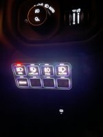
Rather than try to figure out how to retrofit the aux switches, I decided to take the “lazy” option, and got SwitchPros 9100 Module. I also got the SDHQ power module bracket which mounts between the PDC and the headlight. The SDHQ keypad mount kit was easy too, simply replaces the trim panel below the headlight switch. Could I have drilled the holes myself in my own panel, sure. But it made installation that much less of a headache.

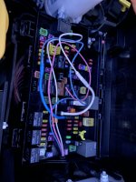
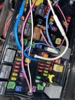
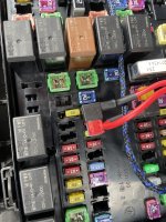
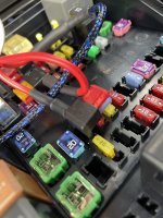
I tapped the Clearance Lights fuse for the lights Trigger wire (dims keypad backlight), and tapped the fuse for “inverter wakeup module, rear usb, and wireless charger” for the ignition-on signal. I need to shorten those wires up a bit later, it’s a bit sloppy in the fuse panel still.

I needed a longer 4awg wire for the power supply, and one with a 5/16” hole for the HAPP stud... I ordered one from Amazon. The HAPP stud needs an M8x1.25
I used a Daystar firewall grommet thru the clutch block off plate to pass wires.

I used the RGB wheel in the app and was able to dial the color(it’s white with a bit of blue tone) and brightness in pretty spot on.

Next I need to start to connect accessories to it...first will be ARB compressor(it will go under rear seat) & the rock Lights. I don’t have reverse or a-pillar lights yet, but now I have an excuse to get them.
Really clean oem look.
 

el_barto

Well-Known Member
Joined
May 25, 2020
Messages
1,245
Reaction score
1,809
Another side note for anyone curious: SP hooked me up with the “RCR Touch 8” keypad cover. I really like that it adds tactile feel to help a) turn on a switch without looking, since the keypad is kind of out of line of sight being down my your knee and b) prevent accidental button activation c) blocks a lot of the light bleed from around the symbol decals.
However, unfortunately, the Amber indicator lights are blocked from line of sight due to the angle of the keypad and the indicator being recessed in the cover.
without Touch Cover
89441DE9-D987-4D47-BF75-A6FAD36DFEF7.jpeg
With Touch Cover (less light bleed)
01C0D46C-54A4-4378-91B8-62558196189B.jpeg

With touch cover from drivers perspective (hard / impossible to see Amber indicator light)
E423ADB5-6678-4485-AA08-92DB491465FC.jpeg
20F83DBE-B4CF-44B1-B916-0DDAA6D94FED.jpeg
 

Robtheelder

Member
Joined
Aug 9, 2021
Messages
52
Reaction score
55
Good job. Nice pictures.
I installed a switch pro in my Tacoma a couple of years ago. The switches are basically mounted in the same location in the Toyota. I found that having the switches that far away from my line of sight was an issue so in the RAM I mounted the switches on a ball mount to the left of the steering wheel, near the top of the dash where I can readily see and access it.

I mounted the heat sink and hardware to the bottom side of the left side engine bay brace. This keeps it out of the way, and high and dry. I attached two terminal blocks to the fuse box cover, one for power from each of the 8 circuits and one for ground. This allows me to easily connect and maintain multiple "out" connectons for an individual switched circuit.

I really like mine. I added led driving lights, high intensity yellow LED fog lights (on a tradesman), four corner emergency flashers, Wet Okle seat warmers, bed mounted 4 ciruit distribution box for bed lights, power ports, USB etc.

I highly recommend the Switch Pro if you have plans for several optional circuits.
 

Users who are viewing this thread

Top