What's new
Ram Heavy Duty Forum

Register a free account today to become a member! Once signed in, you'll be able to participate on this site by adding your own topics and posts, as well as connect with other members through your own private inbox!

Dual Alternator 5kW Inverter Install Problems

Scott C

New Member
Messages
21
Reaction score
10
Points
3
Apologies in advance for the long-ass post! I was wondering if anyone has experienced the problems we are having or might have an idea.

We are building 2022 Ram 2500 Tradesman 4-door trucks with dual 220-amp alternators. We are powering oil and gas testing equipment through a 5kW pure sine wave inverter all located in the back seat of the trucks. We ran 4/0 SGX cable rated at 120C from one alternator to the other, then from the driver-side alternator to a 400A T-fuse, then to the inverter. Our one way cable run is 18-feet not to include the three feet of cable connecting the two alternators. We ran 4/0 SGX ground cable from the inverter back to the alternator mounting bolt to ensure we have a good ground. We used Burndy 4/0 crimp connectors and a 16-ton hydraulics crimper then shrink wrapped the ends and used black or red split wire loom the entire run, except when passing thru the floorboard. We have triple-checked the wiring and have a good ground with a 0.4VDC total voltage drop over the entire circuit.

So far, power is fine at an 18A load on the AC side at both low and high idle. We are having two issues though. One is that the driver-side alternator is providing most of the power instead of the ECM balancing the load between them. The second issue is the voltage is varying all over the place causing the lights to flicker and the AC blower motor to surge. The truck engine is not surging. Our testing system uses Pulse Width Modulation (PWM) to maintain certain levels of heat in our test system. PWM controls a solid state relay that turns on/off in the millisecond range to control the heating elements. What we have noticed is that the voltage is hopping all over the place from 12.6VDC to 14.2VDC as the PWM controller pulses the electrical demand to the 5 heating units. It has to be the PWM as when the system is at full power heating up the various devices, there is no voltage variation and no surging. The voltage fluctuation continues from the batteries even when we shut off the truck, so it isn't the alternators.

We took the truck to the Ram dealer electrician who said there is no reason for the truck to be doing this. He has built a lot of snow plow and ambulance trucks without these problems. He rewired the truck so the 4/0 cable was attached directly to the batteries instead of the alternator with no improvement. He opened a case to get a Ram engineer to weigh in and said it would be 2-3 days before we would get any info, but 2 hours later he received a response that the truck is fine and it must be our equipment. Pretty much a blow off answer and the dealer isn't happy, but not much they can do I guess. The electrician did say that Ram alternators, unlike Duramax and Ford, do not have a voltage regulator and that the ECM manages it for the entire system.

Our current plan is to run 4/0 cable from each alternator directly to the T-400 fuse and see if this will solve the load balance problem. Based on the results of that, we will then look at an external voltage regulator. We are also looking at options other than PWM for temperature control of our equipment, but that won't fix the load balancing problem.

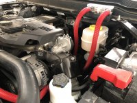
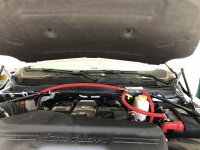
I have attached our current install diagram. The smaller red lines are the OEM 2-gauge wire and the larger ones are 4/0. I did not include the OEM ground wires. I also included a photo of the wiring in the engine compartment.

We would appreciate any thoughts, ideas, or SWAGs since Ram is no help.

Scott
 

Attachments

  • Current Installation.png
    Current Installation.png
    1.7 MB · Views: 74
  • Alt to Fuse.jpg
    Alt to Fuse.jpg
    513 KB · Views: 71
I don't know what RAM's logic is in terms of allocating load per alternator. As for the voltage, I agree with this part where you note that "The voltage fluctuation continues from the batteries even when we shut off the truck, so it isn't the alternators". I that this means it isn't the truck either. Batteries will sag under use, though when the truck shut off I would think you would peak in the high 12s. Perhaps adding a big capacitor as is common for cars with a big stero would smooth it out.
 
with the truck running and the PWM managing the temperature, the voltage fluctuated between 11.6 and 14.4 constantly. With the truck off, it was 11.6 to 12.6-ish.

We tried a 50 farad capacitor and it had no effect at all.
 
If its fluctuating the batteries then id say the inverter may be the issue or the PWM load has to much variance and a large capacitor is needed (more than a 50 farad). Personally i would have added a separate battery bank just for your accessories, i also would switch out the batteries to deep cycles it will handle the load better
 
We tried adding two extra batteries, but still have the flickering lights. That said, we did not isolate the batteries from the truck system, which will be our next option. I don't think this will address the load balancing between the alternators but might fix the light flickering. We can't get any reply from Ram, but I do wonder if the system is supposed to use a primary alternator for power and the secondary one makes up the difference as demand goes up. We have a 2022 Ram 5500 that we are testing this theory on this morning.
 
Alternator balance really does not matter it wont affect your situation
 
Does the voltage on the truck fluctuate with the inverter unhooked?

Does the voltage fluctuate with the inverter hooked up and powered off?

Does the voltage fluctuate with the inverter powered on with a different load than the testing equipment? Such as halogen work lights, heaters, or a heat gun?
 
Without the inverter attached, the voltage holds steady at 13.8.

With the inverter connected and the PID controller running everything at full power to get everything up to operating temperature, so about 21A on the VAC side of the inverter, the voltage holds steady at 13.6.

Once the equipment is up to operating temperature and the PID controller goes into PWM mode, the voltage fluctuates between 12.8 and 14.4 constantly and the lights flicker.

If we turn the truck off while still in PWM mode, the voltage continues to fluctuate but between 12.3 and 13.4-ish.
 
So we changed the cabling. We removed the 4/0 connecting the two alternators then connected each battery to the T-400 fuse with 4/0 cable. From the fuse to the inverter remains the 18' 4/0 cable run. The ground remains the same with a 4/0 cable run to the starter mounting bolt and from the starter mounting bolt to the driver side alternator mounting bolt. We checked the voltage drop from the batteries to the inverter and it was 0.005 each way so 0.01VDC total.

Changing the cabling under the hood fixed the load balancing problem. Both alternators are within 5 amps of each other.

This did not stop the voltage fluctuation, but it did reduce the swing. We removed the 4/0 from the passenger-side battery to see the effect. Load balancing was fine but the fluctuation was from 12.5 to 14.5. We reconnected the 4/0 cable from the passenger-side battery to the fuse and the fluctuation range dropped to 13.2-14.2. The lights still flicker, but everything runs fine.

We did finally find an automotive EE who explained the PWM problem from the PLC through the inverter to the truck and he gave us some suggestions to reduce the fluctuation, but did say that it is not possible to get rid of completely. He also said that it does not hurt the 12VDC-side to fluctuate.

We are going to run the truck all day tomorrow at low high-idle, 1100 rpm, and run through several complete testing sequences to make sure everything works.

I will let you know.

Brutal, is our new wiring what you were talking about when you mentioned HAPP? I am not sure what that is.

HAPP is the stud block on the driver side battery. It's only "rated" (as tested) to 300A. In theory, a hard wire to each batter terminal should get you more combined amps.

Sounds like the cable between the alts was causing the system some grief, AFAIK, they're already common at the HAPP. Just a crazy SWAG theory, but you could have been creating a large inductance load with the wiring loop...

As you're already aware, high current loads need an engine block ground - chassis ground is only good to 50A.


1654214405513.png
 
HAPP is the stud block on the driver side battery. It's only "rated" (as tested) to 300A. In theory, a hard wire to each batter terminal should get you more combined amps.

Sounds like the cable between the alts was causing the system some grief, AFAIK, they're already common at the HAPP. Just a crazy SWAG theory, but you could have been creating a large inductance load with the wiring loop...

As you're already aware, high current loads need an engine block ground - chassis ground is only good to 50A.


View attachment 38905
Piggybacking on this as I am about to install a winch on my truck. Is there a place on the engine block to ground to?
 
We initially tried the frame under the rear seat. Even after grinding down to bare metal, we had a massive voltage drop. We then grounded at a starter mounting bolt, which was better but we still way to much voltage drop. We then ran a jumper from there to the alternator mounting bolt on the driver side alternator and now have 0.001 voltage drop. Not sure why the frame wasn't more conductive considering it is solid all the way to the engine mounts.
 
We ran the truck at 1100RPM high idle for 11 hours today with all of our equipment running with no issues, so I think we are good to go. Produced about 5 gallons of water from the AC too! LOL

The only issue remaining is that, if we shut the truck off then restart, it trips the inverter, which shuts down some of our equipment. This shouldn't be an issue since we don't shut down the truck when out working, but it would be nice not to have to worry about everything having to reboot and recalibrate just in case. We are going to see if possibly adding larger CCA batteries would prevent the voltage from dropping below the inverter's 10-volt trip. If not, then we might look into adding a deep cycle battery at the inverter and route the cables to the battery then to the inverter. We would add a voltage regulator as well to keep the truck from drawing on that battery. A lot more hassle, so we hope the larger batteries in the truck will work.
 
You may have access to better gear, but I've had good luck with the Bluesea ACR stuff.

They have one rated to 500A


Thanks I will have a look at that! Our T-400 fuse blocks are Blue Sea. Really good quality stuff from them. We get our 4/0 SGX copper cable and Burndy tin plated copper lugs from Nassau Cable Company. (https://nassaunationalcable.com/) Best prices we have been able to find for high quality battery cable.
 
Thanks I will have a look at that! Our T-400 fuse blocks are Blue Sea. Really good quality stuff from them. We get our 4/0 SGX copper cable and Burndy tin plated copper lugs from Nassau Cable Company. (https://nassaunationalcable.com/) Best prices we have been able to find for high quality battery cable.

I have the smaller SI series ACR setup for the dual batteries I put in my little SeaDoo jet boat and it's been running strong for 8 years now. Had to wire up a diode circuit to allow starting/charging properly with 2 engines and batteries. One start and one house also wired through a 1/2/Combine switch. Had to put my thinking cap on for that one.
 
Brutal, thanks for pointing out the HAPP! Other than not being able to use the plastic cover over the terminals, it is much easier to connect there than anywhere else.

We wired up the 5500 yesterday based on all the lessons learned with the 2500. 4/0 from each battery to the 400A T-Fuse, then 4/0 to the inverter in the rear seat, then back to the starter mounting bolt. We tried the mounting bolt again and tested the voltage drop under load. 0.001 each way so we are grounded! Here is what she looks like.

It was a PITA getting it into the rear of the cab. On the 5500, being a cab-and-chassis, the DEF tank is right under the driver side rear seat, which is where we came up in the 2500. We had to go past the tank and come back into the small storage bin from the rear that added about 18" to the run.
 

Attachments

  • 2022 Ram 5500 Pic-1.jpg
    2022 Ram 5500 Pic-1.jpg
    451.9 KB · Views: 56
  • 2022 Ram 5500 Pic-2.jpg
    2022 Ram 5500 Pic-2.jpg
    458.9 KB · Views: 53
Hopefully, the HAPP can carry the current you need.

I mean, given it's connected the the + terminal, and there's a 250A shunt in there, it should be GTG.
 
Back
Top