What's new
Ram Heavy Duty Forum

Register a free account today to become a member! Once signed in, you'll be able to participate on this site by adding your own topics and posts, as well as connect with other members through your own private inbox!

Aux Switches

Exactly what I was wondering......I have the large positive cable connected, but there was no separate ground for the Aux PDC. I will add that ground and see if that works.

I am so close....switches are active, commercial settings menu enabled.....just need power out of one of the wires. I have some time tomorrow after work to add that ground.

Thanks!!!

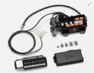
To be clear, I'm not sure where the grounds are needed (in diagram below), but that's the first thing I'd be looking for.

Can you get power between one of the plug ports and the ground on light grey pin 3?

Also, perhaps you were already aware, but the AUX switches only complete ground, which energizes the relay in the Aux PDC that sends 12V to the connector.


1759360344422.png
 
Pretty sure the G907A ground is only if you're also building the BAT+/IGN+ pass-thru circuits into the cab (D2621A)

You should be getting what you need for ground through a chassis point connection at your device. I don't think the AUX switches would light up or work if they didn't have ground.
 
Pretty sure the G907A ground is only if you're also building the BAT+/IGN+ pass-thru circuits into the cab (D2621A)

You should be getting what you need for ground through a chassis point connection at your device. I don't think the AUX switches would light up or work if they didn't have ground.
Thanks for the schematic......never had that. I don't have G911A connected...I don't even remember seeing that coming out of the PDC. I will have to take another look. I did know about the switch just sending ground to activate the circuit coming out of the PDC...jusr FYI..the switch lights started working after I activated them in AlphaOBD. I guess I am taking it out over the weekend to have another look.
 
Thanks for the schematic......never had that. I don't have G911A connected...I don't even remember seeing that coming out of the PDC. I will have to take another look. I did know about the switch just sending ground to activate the circuit coming out of the PDC...jusr FYI..the switch lights started working after I activated them in AlphaOBD. I guess I am taking it out over the weekend to have another look.

G911A is on the AUX switch bank. I'd expect it's connected to the harness, but if you added all that, you may have missed a ground.

What kit is this? One you got from @RHD_Godzilla or built yourself?
 
G911A is on the AUX switch bank. I'd expect it's connected to the harness, but if you added all that, you may have missed a ground.

What kit is this? One you got from @RHD_Godzilla or built yourself?
I bought this: Genuine Mopar Auxiliary Switch Kit 82216450AB. It says nothing about another ground and it looks like there are no other wires other than the brown wires for the switch bank and the posiitve battery connection.
 

Attachments

  • aux kit.jpg
    aux kit.jpg
    47.6 KB · Views: 20
  • aux sw.jpeg
    aux sw.jpeg
    523.8 KB · Views: 16
I took the PDC out today to make sure I didn't miss anything. It is sealed from the bottom and only the positive cable and the harness going in to the switches comes out. The relays are getting ground when you activate the corresponding aux switch so that's not it. i found power inside the PDC right about when the cable comes in, but there is no power at ANY of the connections at the relays, so they are obviously not activating when an aux switch is pressed. I found this schematic, but noted a few connections that I don't have and don't know if I need. Attached. I am hoping someone has some ideas where to go next.
 

Attachments

  • connections from PDC.jpg
    connections from PDC.jpg
    98.8 KB · Views: 15
Has anybody installed the 82216450AB kit????

 
I expect you'll need power on the other side of the relay coil.

Did the kit not come with any instructions or wiring diagrams?

1760041357579.png
 
I expect you'll need power on the other side of the relay coil.

Did the kit not come with any instructions or wiring diagrams?
No real instructions came with it, but I attached a pic of the kit. There is a large wire for direct power to the battery and the smaller harness which runs inside to the switch bank. The six small brown wires send ground to the corresponding relay when the switch is activated. i checked and that works. I also attached the schematic with some notes on it. I am missing something, but who knows what......I get power inside the aux PDC, but nothing at the relays. What is the 2 wires in your pic?? I have nothing to connect them to at the PDC.
 

Attachments

  • connections from PDC.jpg
    connections from PDC.jpg
    98.8 KB · Views: 10
  • aux kit.jpg
    aux kit.jpg
    47.6 KB · Views: 10
No real instructions came with it, but I attached a pic of the kit. There is a large wire for direct power to the battery and the smaller harness which runs inside to the switch bank. The six small brown wires send ground to the corresponding relay when the switch is activated. i checked and that works. I also attached the schematic with some notes on it. I am missing something, but who knows what......I get power inside the aux PDC, but nothing at the relays. What is the 2 wires in your pic?? I have nothing to connect them to at the PDC.

If the relay doesn't engage, then it doesn't have 12V power to the B+ side of the coil [Y]. That should be connected to a power source as well (low current draw). AFAICT, that's pin 31 on the PDC connector and should be fused. I don't have access to any more info than that.

[M], used for power to the ignition only relay for circuit F606 would get power from pin 34 (a switched ignition 12V source) in the PDC.

I expect you're doing this work with access to a multimeter and can check/probe for ground continuity, 12V, etc.?
I have the tools...but what I think I hear is that I have to take apart the PDC and make connections inside?? The unit came fully assembled, harness wire tied with only the wires I described. There are no additional connections unless I need to make them under the board that the relays are plugged in to. This is exactly what it looked like. No additional wires coming out to connect to what you describe. And the instructions make no mention of any other wiring. Please confirm. But if that's what needs to happen I have no issues doing that---sucks of Mopar to make this a puzzle. Now big rain all this weekend so cant do anything......need the weather to break.

1760096716420.png
 
I have the tools...but what I think I hear is that I have to take apart the PDC and make connections inside?? The unit came fully assembled, harness wire tied with only the wires I described. There are no additional connections unless I need to make them under the board that the relays are plugged in to. This is exactly what it looked like. No additional wires coming out to connect to what you describe. And the instructions make no mention of any other wiring. Please confirm. But if that's what needs to happen I have no issues doing that---sucks of Mopar to make this a puzzle. Now big rain all this weekend so cant do anything......need the weather to break.

View attachment 90307

Pic of underside wiring?

Is the POS side of the relay coil wired to anything? I suppose they could have run them off the main B+ cable, but it would HAVE to be fused. Find that connection... Did you move any fuses?
 
Pic of underside wiring?

Is the POS side of the relay coil wired to anything? I suppose they could have run them off the main B+ cable, but it would HAVE to be fused. Find that connection... Did you move any fuses?
Didn't move anything..this is exactly how it came and how it looks now....Do I need to take this insert out and investigate the wiring below??? All the wiring coming out of the bottom is nicely tie wrapped...I would hate to think Mopar wanted me to disassemble it. But I'll do what I have to.

1760123725316.png
 
Didn't move anything..this is exactly how it came and how it looks now....Do I need to take this insert out and investigate the wiring below??? All the wiring coming out of the bottom is nicely tie wrapped...I would hate to think Mopar wanted me to disassemble it. But I'll do what I have to.

View attachment 90316

Pull one relay and one fuse and check that all positions are pinned.

Pull the B+ power lead off the battery/HAPP where connected so there's no power going into the box and do a continuity check between the B+ lead and the fuse leads and relay leads to map out where the power is present. Same for grounds.

I have a feeling the "kit" is incomplete or (likely) wired different than factory. The 20A fuse on the far left is NOT is the same place that's shown in the docs that's for the "Run Only". I suspect it *MAY be the fuse for the 12V supply to the relays. is that fuse good? I found the install instructions in a thread on 5thgenrams and don't see where there's anything else to do besides pinning in the 6 switch ground wires and the B+ power connection.

Here's the factory layout of the AUX PDC:

1760128666758.png
 
Pull one relay and one fuse and check that all positions are pinned.

Pull the B+ power lead off the battery/HAPP where connected so there's no power going into the box and do a continuity check between the B+ lead and the fuse leads and relay leads to map out where the power is present. Same for grounds.

I have a feeling the "kit" is incomplete or (likely) wired different than factory. The 20A fuse on the far left is NOT is the same place that's shown in the docs that's for the "Run Only". I suspect it *MAY be the fuse for the 12V supply to the relays. is that fuse good? I found the install instructions in a thread on 5thgenrams and don't see where there's anything else to do besides pinning in the 6 switch ground wires and the B+ power connection.

Here's the factory layout of the AUX PDC:
I'm glad you found the instructions and see I'm not nuts.....that was the next thing I was going to attach. As you saw, it shows a very simple hook up that you would think should work. I appreciate the help and ideas. Maybe the far left fuse is the culprit. That would be nice. I have pulled the relays and they are all pinned, but don't have any power at any of the pins with the B+ wire connected. I do get ground at the relay when the corresponding aux switch is activated. Since the weather is crap this weekend I am going to have to wait until one night next week to continue this.......Thanks again and I will update when I can with my next findings.
 
Pull one relay and one fuse and check that all positions are pinned.

Pull the B+ power lead off the battery/HAPP where connected so there's no power going into the box and do a continuity check between the B+ lead and the fuse leads and relay leads to map out where the power is present. Same for grounds.

I have a feeling the "kit" is incomplete or (likely) wired different than factory. The 20A fuse on the far left is NOT is the same place that's shown in the docs that's for the "Run Only". I suspect it *MAY be the fuse for the 12V supply to the relays. is that fuse good? I found the install instructions in a thread on 5thgenrams and don't see where there's anything else to do besides pinning in the 6 switch ground wires and th
I know the relays are all pinned. I just ran out there and looked again. The fuse is in position 4 as my picture shows. The spot to the right that your diagram has a fuse in, has only one pin with no power at it. Maybe I try getting in touch with Mopar ( a long shot) to see they could assist or maybe I got a defective kit...or I remember seeing someone who built their own. If I take the board out of the housing I should be able to trace or move wiring as needed to make this thing work as designed. Not sure what else to do at this point.
 
I know the relays are all pinned. I just ran out there and looked again. The fuse is in position 4 as my picture shows. The spot to the right that your diagram has a fuse in, has only one pin with no power at it. Maybe I try getting in touch with Mopar ( a long shot) to see they could assist or maybe I got a defective kit...or I remember seeing someone who built their own. If I take the board out of the housing I should be able to trace or move wiring as needed to make this thing work as designed. Not sure what else to do at this point.
There is another 6 pin harness you may need, or there is this kit which may help;
1760212482349.png

Also on u-tube RAM TRUCKS RAM ENGINEERING, RAM has several videos pertaining to the aux switches.
 
There is another 6 pin harness you may need, or there is this kit which may help;


Also on u-tube RAM TRUCKS RAM ENGINEERING, RAM has several videos pertaining to the aux switches.
I have that kit but couldn't find anything on what to do with the rest of the wires
It includes the wires that you plug into the light gray and dark gray connectors on the PDC to power the accessories. I will check youtube. Thanksl
 
There is another 6 pin harness you may need, or there is this kit which may help;
View attachment 90335

Also on u-tube RAM TRUCKS RAM ENGINEERING, RAM has several videos pertaining to the aux switches.

That's the wiring kit bundle for all AUX Switch equipped trucks. It's the "external" wiring for connecting stuff to the aux ports, adding pass-thru wiring jumpers in he cab, and the extra pass-thru wiring the 21+ trucks come with. It has nothing to do with the installed AUX PDC.
 
I know the relays are all pinned. I just ran out there and looked again. The fuse is in position 4 as my picture shows. The spot to the right that your diagram has a fuse in, has only one pin with no power at it. Maybe I try getting in touch with Mopar ( a long shot) to see they could assist or maybe I got a defective kit...or I remember seeing someone who built their own. If I take the board out of the housing I should be able to trace or move wiring as needed to make this thing work as designed. Not sure what else to do at this point.

I'm confused. Does the fuse position #4 have 2 pins? Is there power on one of them with B+ hooked up?

Does the + side of the relay coil have continuity to the B+ cable? (again, pull B+ main lead off the battery to check!)


1760219533622.png
 
Back
Top