What's new
Ram Heavy Duty Forum

Register a free account today to become a member! Once signed in, you'll be able to participate on this site by adding your own topics and posts, as well as connect with other members through your own private inbox!

Aux Switch wiring location

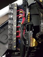
Would you be kind enough to post the pinout of the large connector please.

Are you referring to the large connector above the spare tire in this picture?

I don't have wiring diagrams that show the pinout of this connector. Someone with a Tech Authority subscription may be able to lookup the pinout.

EDIT: This is all I know about the connector. In the upfitter guide, it is listed as Y/X 960 with pin 5 being the rd/white and pin4 being the pink/orange.

1591124949776.png
 
It was labelled XY125A
DlOALYg.jpg
CYb1FBk.jpg
 
I was looking for the rear connector the other day when cleaning the car, given folks have cited trouble identifying it (though perhaps it’s solved above?) in the exact location cited though I see this.

Any ideas?

79a16fcc6e16c5e802fa82d0dfcff7e1.jpg


Sent from my iPhone using Tapatalk
 
Sorry, I stuffed up. Thank you I do need the one posted and I am also trying to find the cables to connect in the relays for the AUX 1 - AUX 6 switches. The diagram had this labelled as 125A. Sorry for mucking you about. Appreciate your kind assistance.
 
That's the one, Jimmy you are a life saver. Thanks again for your kind assistance. Will post how it all goes, the replacement switch is on order so I can at least wire the rest.
 
I was looking for the rear connector the other day when cleaning the car, given folks have cited trouble identifying it (though perhaps it’s solved above?) in the exact location cited though I see this.

Any ideas?

79a16fcc6e16c5e802fa82d0dfcff7e1.jpg


Sent from my iPhone using Tapatalk

Well known Trailer TPMS receiver plug,
 
@Jimmy07 Thanks for posting the pinout of XY960A. It confirms what I suspected which is that pin 16 (W750) is also a BATTERY feed, and it is a bigger wire than the BATTERY feed on pin 5. Are you able to determine which fuse protects W750 and what W750 normally feeds?

1591162954555.png
 
@Jimmy07 Thanks for posting the pinout of XY960A. It confirms what I suspected which is that pin 16 (W750) is also a BATTERY feed, and it is a bigger wire than the BATTERY feed on pin 5. Are you able to determine which fuse protects W750 and what W750 normally feeds?

View attachment 4984
That one is fuse F30, and it is the BATT+ pin on the 7-way trailer connector.
 
had a look at the Aux PDC and the aux 1-6 cables not present. I cannot physically get to XY125A so my options are limited. Will have to run a cable from the Aux PDC and splice into the cable where it plugs into the aux switch bank D2321A. Then it’s chase the bits to install the relays and fuses into the PDC.
 
Those two blunt cut wires are BAT+ and IGN and come from the AUX PDC. You have to plug in the Light Grey jumper harness that came in the upfitter wiring bag into the connector under the dash to bring power to them in the rear. In that under dash jumper is an additional blunt cut wire that is on a "pass thru" circuit (G425). You could repin the jumper and wires to carry that pass thru circuit to the rear on one of the others. Then under the hood, you loop one of the aux switches to the pass through pin (it's on the same set of Aux plugs.)

I did this tonight on my 2020. Worked out great. My plan is to install some Black Oak LED flush mount lights in the rear bumper. I had bought them for the 2016 I had previously. But I could never figure the wiring to get it to work with the AUX switches it had.
Below is a diagram of what I did which is what brutal posted back on May 28th. I had my gf turn on and off AUX6 switch while I tested the wire at the rear. Now that I have that taken care of, I can go about removing the bumper to cut holes for the lights and get them installed soon. That will be the hard part, cutting holes into the bumper. Thankfully they are not metal anymore like my 2016 was. So it shouldn't be too hard to get the holes in and lights installed.

Thank you brutal for the suggestion on the wiring solution.

AUX6.JPG
 
Nice work on this everyone.

I did a pin swap on the D connector as well, but swapped 1 and 5 so the IGN switched feed went back into the engine compartment, which I then ran to the coil terminal of a large 300A constant duty relay, which takes a 2AWG battery feed back to an Andersen connector at the rear bumper for my 60A Renogy DC-DC charger for my Airstream.
 
The Upfitter cabling was not included in my 2500 and the PDC had vacant slots (no cables). Fitted the 6 AUX switch assembly, spliced into each AUX sense wire at the back of the Aux Switch Bank Upper D2321A where the wires exist the connector going to XY125A. The splice was six inches away from the D2321A plug. These were AUX 1 to AUX 6 (Relay Sense) wires. I ran the spliced cable through the firewall (Trailer 7 core cable) and wired this to the standard automotive relays.

I found that when you press the AUX buttons the relay sense goes to ground. I wired pin 86 (via a fuse) to battery power and pin 85 to the relevant AUX relay sense.

All works perfectly thanks to the information in this forum.

The rear of my manufactured AUX relay assembly is rather busy but easily assembled using relay sockets available from any automobile parts outlet.
 

Attachments

  • AUX Relay assembly.jpg
    AUX Relay assembly.jpg
    323.3 KB · Views: 94
I just did some re-wiring on my 20yr old motorcycle and it was a headache (for me)... that would drive me nuts!
Looks good though!
 
Earlier in this thread, I mentioned I was working on a YouTube video on the AUX switches. I haven't finished editing the video, but I decided to publish a preview for feedback.

See this post.
 
The Upfitter cabling was not included in my 2500 and the PDC had vacant slots (no cables). Fitted the 6 AUX switch assembly, spliced into each AUX sense wire at the back of the Aux Switch Bank Upper D2321A where the wires exist the connector going to XY125A. The splice was six inches away from the D2321A plug. These were AUX 1 to AUX 6 (Relay Sense) wires. I ran the spliced cable through the firewall (Trailer 7 core cable) and wired this to the standard automotive relays.

I found that when you press the AUX buttons the relay sense goes to ground. I wired pin 86 (via a fuse) to battery power and pin 85 to the relevant AUX relay sense.

All works perfectly thanks to the information in this forum.

The rear of my manufactured AUX relay assembly is rather busy but easily assembled using relay sockets available from any automobile parts outlet.
Just an fyi if your ever doing something like this again becaise of the minimal load on the relay coil trigger you can use cat5 cable to go through the firewall nice and small and can handle the load required....
 
Back
Top