What's new
Ram Heavy Duty Forum

Register a free account today to become a member! Once signed in, you'll be able to participate on this site by adding your own topics and posts, as well as connect with other members through your own private inbox!

Removing pins from 12v connector

StadlerMat

New Member
Messages
18
Reaction score
5
Points
3
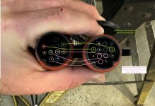
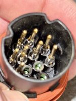
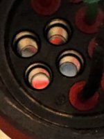
Hi ya'll. Does anyone have experience with removing the pins from the 12 pin connector. I had no issue dissembling the housing down to where I could see the back wires going into the terminals that serve as pins on the front. My experience is that there is usually little wings that have to be pressed in to allow the terminal loose from the connector. Some are in the front, some are in the back but on this connector there doesn't appear to be either. Looking on the SAE site for this connector type and on a sub supplier product page led me to this image which looks to me to be a one time use compression fitting that goes on to the wire (usually with an adhesive) and is pressed in to the terminal which then locks. However I've read several people mention "re-pinning" the 12v connector so I'm hoping i'm missing something.

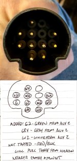
What I'm doing is in image below "splice" joining the TVSCM connector with the Aux 2 camera.

the connector btw... who in the world thinks this pin arrangement makes sense. lol

Any input? Anyone successfully done this and can tell me how?
 

Attachments

  • splice.jpg
    splice.jpg
    335.8 KB · Views: 37
  • 12 pin connections.jpg
    12 pin connections.jpg
    83.1 KB · Views: 33
  • connector arrangement.jpg
    connector arrangement.jpg
    134 KB · Views: 33
I don't have any useful info but this has been on my to-do list, adding an aux2 interior camera to my trailer surround.
 
Looks like you need a barrel style depinning set
Maybe. The barrel terminating tools in my set couldn’t slide in the way it normally works. I’m concerned that the SAE spec on the connector means that it’s a sleeve type that is epoxy bonded into a sleeve which then presses with a compression tip into the open end of the pin and once the epoxy is set it’s truly one use. That’s why I was curious if anyone has successfully done it.
 
Maybe. The barrel terminating tools in my set couldn’t slide in the way it normally works. I’m concerned that the SAE spec on the connector means that it’s a sleeve type that is epoxy bonded into a sleeve which then presses with a compression tip into the open end of the pin and once the epoxy is set it’s truly one use. That’s why I was curious if anyone has successfully done it.
Definitely no epoxy, it’s just barrel terminals with seals, or cavity plug inserts for empty locations.
@Webracin hasn’t been on here in a few months, but I instructed him on doing the same thing you are trying to do. He got it done, but didn’t detail the actual process. Here’s a pic he sent me of the terminals depinned. It’s just a matter of diving in, start disassembling the plug, and finding the right size barrel depin key (I use a kit from Amazon that was ~$8 and contains about 50 different depin tools).

IMG_0234.jpeg
 
I had no trouble depinning with a cheap amazon multi-tool set.

There's no epoxy/potting or anything, just silicon seals.
 
I had no trouble depinning with a cheap amazon multi-tool set.

There's no epoxy/potting or anything, just silicon seals.
I see the issue now. That picture held a lot. Thanks.
 
Ok. Got it done. For those that want to do this themselves this is how I found easiest to do it.

- remove screws from back of 12 pin
- slide watertight gasket clear of rear section and then slide back rear section to give yourself room to work.
- cut 2” or so of the heat shrink to give yourself a little room in the wires.
- use needle nose pliers to pull black tab on 2 pin seal away from backside of wire connection to terminals
- use rounded end pry tool to remove black cover from front end of 12 pin terminal exposing the front of the pins
- gently pull pins out the front one by one, compress the ears and then slide them back out the back
- raise the ears back up before you forget
- use blunt end pry tool or paperclip/terminating pin etc to push green silicon terminal gaskets to block dead pin locations
- then add the green / white / gray wires back in as shown below.

Once I realized from @Jimmy07 photo this am that the ears faced rearward (I assumed before that they faced forward like a military 12 pin does) and tried it this way it took me about 30 minutes to do the whole thing. Tested it a bit ago and it works so huzzah.

Side note - rather than splice the red / black into the red / black wires for power and ground from the TSVCM side I am using a power and ground that is next to where I am mounting the camera in my toy hauler garage as I already put those in the wall there for when I had a furrion wireless camera there but that’s personal choice. You also could tie in with a 2/1 splice into the black and red from the 12 pin.

Either way once your done and have all your red/white/green waterproof seals On the back of your terminal pins drop them In place and make sure they pull back through to the correct height and the tabs catch. Then slide the seal on the front and backside of the 12 pin, wrap the wire that you removed the weatherstripping from with some tape, slide the rear portion of the 12 pin back into place, re-inset the white gasket and tighten down.

Thanks for the help and hopefully this is helpful to others in the future.
 

Attachments

  • IMG_1154.jpeg
    IMG_1154.jpeg
    307.8 KB · Views: 9
  • IMG_1151.jpeg
    IMG_1151.jpeg
    222.6 KB · Views: 11
  • IMG_1146.jpeg
    IMG_1146.jpeg
    352.4 KB · Views: 11
  • IMG_1147.jpeg
    IMG_1147.jpeg
    167.6 KB · Views: 11
Back
Top