
Ram Heavy Duty Forum
You are using an out of date browser. It may not display this or other websites correctly.
You should upgrade or use an alternative browser.
You should upgrade or use an alternative browser.
mopar Power Deployable Running Boards
- Thread starter johanh13
- Start date
b307a1
Well-Known Member
I am pretty sure they are made by AMP Research for Ram. I put them on my '15 and '17 crew cabs. You can get them from a lot of sources like ebay,,,,,$1399 w/ free shipping.
Burn'n Oil
It's a metaphor!
Have you queried a dealer? They typically deal with lotsa MOPAR parts.
johanh13
Active Member
- Joined
- Aug 10, 2019
- Messages
- 177
- Reaction score
- 102
Yeah, I called my local dealer, and they said they are not yet available for the 2500, but they are coming. They sell the mopar kit for the 1500 for $1,499 and flashing the controls is $185, they told me it would be similar on the 2500... does anybody else have more definitive words on this?
Last edited:
johanh13
Active Member
- Joined
- Aug 10, 2019
- Messages
- 177
- Reaction score
- 102
So my dealer finally quoted me the parts to install the power deployable running boards;
68361654aa power running board, right
68361655aa power running board, left
68367399ae controller module
68410914ad chassis wiring, left
68385176ae chassis wiring, right
Everything makes sense, except I cannot see where to install the controller module.
Does anyone know where it goes? I am assuming under the dash somewhere? Is there another wire harness that would need to be swapped to get the connections for the module?
If anyone has a 2019 or 2020 Ram 2500 with factory power running boards, do you have any ideas on this? Thanks in advance
thestuarts
Well-Known Member
- Joined
- Jun 10, 2019
- Messages
- 498
- Reaction score
- 499
Does anyone know where it goes? I am assuming under the dash somewhere? Is there another wire harness that would need to be swapped to get the connections for the module?
I have the Tech Authority manual for the 2019 Ram 3500, so the installation location may be different for a 2500. According to the diagram, the PSSM seems to be located at position (3) near the rear-view mirror on the passenger's side, BUT the verbal description says it is under the steering column. Choose your own adventure.


johanh13
Active Member
- Joined
- Aug 10, 2019
- Messages
- 177
- Reaction score
- 102
I have the Tech Authority manual for the 2019 Ram 3500, so the installation location may be different for a 2500. According to the diagram, the PSSM seems to be located at position (3) near the rear-view mirror on the passenger's side, BUT the verbal description says it is under the steering column. Choose your own adventure.
View attachment 4764
View attachment 4766
View attachment 4765View attachment 4768
Thank you very much, this will help a lot!
thestuarts
Well-Known Member
- Joined
- Jun 10, 2019
- Messages
- 498
- Reaction score
- 499
The diagram is correct. I located part 68367399ae on my truck by removing the glove box (follow the instructions in this video). The PSSM is located between the glove box and the passenger's side fender just below the side-view mirror.

thestuarts
Well-Known Member
- Joined
- Jun 10, 2019
- Messages
- 498
- Reaction score
- 499
Ok, so with your help, I found the location for the PSSM. However, there are no connectors to plug the module in, looks like it is part of the main dashboard wiring harness... thanks for all your help!
The Tech Authority supplemental information I have does not contain the wiring diagrams, unfortunately. You'll need someone with an online subscription to Tech Authority to help with the wiring diagrams. @Jimmy07 may be able to help locate the wiring for the PSSM.
In order to do this practically, you’re going to have to build some custom wiring harnesses. Without having you do some extensive exploratory work, I’m guessing none of the connectors or wires will be populated on a 2500. Those two chassis harnesses are only half of what you need and those are almost $500. To replace them, you’d need to lift the bed to remove and replace the existing ones. Then there’s the dash harness that carries the two connectors that plug into the PSSM. If your lucky, they might be there.
Not sure how you plan on enabling them, but it’s probably going to have to be with AlfaOBD. I doubt the sales code will be available to add to your truck when the dealer hooks up their witech to it. Let me know if you want me to look into it further to figure out the easiest way to add the wiring.
Not sure how you plan on enabling them, but it’s probably going to have to be with AlfaOBD. I doubt the sales code will be available to add to your truck when the dealer hooks up their witech to it. Let me know if you want me to look into it further to figure out the easiest way to add the wiring.
johanh13
Active Member
- Joined
- Aug 10, 2019
- Messages
- 177
- Reaction score
- 102
In order to do this practically, you’re going to have to build some custom wiring harnesses. Without having you do some extensive exploratory work, I’m guessing none of the connectors or wires will be populated on a 2500. Those two chassis harnesses are only half of what you need and those are almost $500. To replace them, you’d need to lift the bed to remove and replace the existing ones. Then there’s the dash harness that carries the two connectors that plug into the PSSM. If your lucky, they might be there.
Not sure how you plan on enabling them, but it’s probably going to have to be with AlfaOBD. I doubt the sales code will be available to add to your truck when the dealer hooks up their witech to it. Let me know if you want me to look into it further to figure out the easiest way to add the wiring.
I would be very curious to see what a custom wiring harness would consist of! I already checked, my truck does not have the connectors for the PSSM. I will hold off on buying any parts and making any decisions about the running boards until I hear more from you, thanks
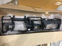
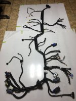
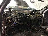
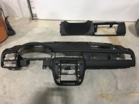
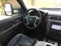
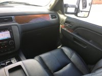
On a [somewhat] related note, a few years ago I did an interior swap on a 2011 GMC Sierra 2500HD. I went from an SLE to SLT; I added the NAV, bose, subwoofer, console, heated power leather bucket seats, door panels, et cetera. This was extremely in-depth and I used all OEM parts and EVERYTHING worked when I was done. Attached are a few photos of some of the parts I used and the finished product.... I am not saying though I want to do something this involved again.
Attachments
Sorry, just noticed the alert for this thread. I will look into this for you, just give me a day or two.I would be very curious to see what a custom wiring harness would consist of! I already checked, my truck does not have the connectors for the PSSM. I will hold off on buying any parts and making any decisions about the running boards until I hear more from you, thanks
On a [somewhat] related note, a few years ago I did an interior swap on a 2011 GMC Sierra 2500HD. I went from an SLE to SLT; I added the NAV, bose, subwoofer, console, heated power leather bucket seats, door panels, et cetera. This was extremely in-depth and I used all OEM parts and EVERYTHING worked when I was done. Attached are a few photos of some of the parts I used and the finished product.... I am not saying though I want to do something this involved again.
johanh13
Active Member
- Joined
- Aug 10, 2019
- Messages
- 177
- Reaction score
- 102
Hey Jimmy07, maybe you can answer a few other questions for me? So I found this dash harness & description (see below), does that have anything to do with how many speakers my truck has? I have the 9 speaker alpine system. Also, is my 8.4 NAV "disassociated" ?
part number
68410820AD
description
[Instrument Panel Parts Module], [Disassociated Touchscreen Display], [Bucket Seats], [Overhead Ambient Surround Lighting], [Power Adjustable Pedals w/Memory], [Power Deployable Running Boards].
part number
68410820AD
description
[Instrument Panel Parts Module], [Disassociated Touchscreen Display], [Bucket Seats], [Overhead Ambient Surround Lighting], [Power Adjustable Pedals w/Memory], [Power Deployable Running Boards].
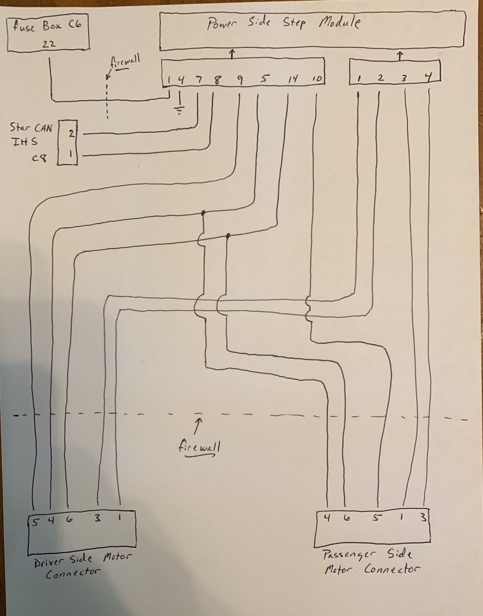
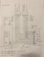
Here’s some info I put together on the power steps. It includes the schematic, connector views, and pinouts. The wire sizes are listed in mm2, so convert those to AWG when choosing wire. https://drive.google.com/file/d/1aWISv7rrkxYO31HQMoymEi8AOSLDDUv3/view?usp=drivesdk
The way I would do this is, I would install all the parts first, then the harness. Using your best guess, cut all the wires long enough (longer) to reach their appropriate spots with all wires originating at the power step module. This method will bypass all inline connectors, and remove all doubt on what partial wiring may or may not be present. If the fuse box C6 connector pin 22 wire is already present, just remove it and install your wire. No sense in figuring out which connector it terminates at, and adding more terminal part numbers in the mix. Assemble the wires to the C1 and C2 power step module connectors, and leave the other connectors off for now so you can pass the wire bundle through one location in the firewall that you choose. Then, once you branch off the wiring to go to the two motor connectors and fuse box connector, cut them to length and finish pinning the wires to the rest of the connectors. Attach the ground wire near the power step module, as there will already be a common ground bolt at the footwell in that vicinity. There are detailed pics of the star can IHS connector block location in the above document.
Use Tesa tape for interior wiring, and use super 33 tape and split loom for exterior wiring.
I’m no good at doing drawings on a computer, but here’s a crude sketch-
Here’s all the parts you need to build the harness:
(1) Power distribution center C6 connector terminal- Yazaki 7116-4120-02
(1) power step module C1 connector- Yazaki 7283-8398-40
(4) power step module C1 connector terminals- Yazaki 7116-4110-02
(1) power step module C2 connector- Yazaki 7283-8599-30
(2) step module C2 connector large terminals- Yazaki 7116-4110-02 (same as C1 terminals, so 6 all together)
(6) step module C2 connector small terminals- Yazaki 7116-4720-02
(2) step motor connectors- molex 33472-0606- https://www.mouser.com/ProductDetail/Molex/33472-0606?qs=/ha2pyFaduiWXvgSsHwiNBIIkoY4qjlCTZRPTiQXtAg=
(10) step motor connector terminals- molex 33012-2002- https://www.mouser.com/ProductDetail/Molex/33012-2002-Loose-Piece?qs=8%2Bu/V6/T1Oo1Ad3cHZ5LpA==
(2) step motor connector empty position seal plugs- molex 34345-0001- https://www.mouser.com/ProductDetail/Molex/34345-0001?qs=6RXNyJqNVR55nh5VsmiX%2Bg==
(1) star can IHS connector- TE Connctivity 2-2138650-1 - https://www.mouser.com/ProductDetail/TE-Connectivity/2-2138650-1?qs=/ha2pyFadujST6z4YULS%2BBJCiH9ln5rUAcHQ5fUP85DrTD0eioaUpg==
(2) star can IHS connector terminals- TE Connectivity 5-963715-1 - https://www.mouser.com/ProductDetail/TE-Connectivity/5-963715-1-Cut-Strip?qs=0lQeLiL1qybbw60VBbVFhw==
(These are only available in 100 quantities at mouser. I can mail you some in a standard letter if you want)
A note about obtaining Yazaki parts:
Yazaki parts are hard to come by in small quantities. SMD Inc is your best bet, but they require a $100 minimum order. I would call them first and see if they’ll give you “samples” of all the Yazaki parts needed. If this doesn’t work, let me know and I can put together a group buy with some other people.
Miscellaneous wire harness parts:
Excellent source for automotive wire- https://4rcustomswire.com/
Firewall boot- https://www.amazon.com/Daystar-Univ...e&sr=1-1-191b1ae3-0539-4250-ad39-b698e0b800f6
Terminal crimper- https://www.amazon.com/IWISS-Profes...minal+crimp+tool+dupont&qid=1590935939&sr=8-3
Tesa tape
Super 33 tape
1/4” split wire loom
1/8” heat shrink tubing
johanh13
Active Member
- Joined
- Aug 10, 2019
- Messages
- 177
- Reaction score
- 102
Burn'n Oil
It's a metaphor!

Users who are viewing this thread
Total: 1 (members: 0, guests: 1)