Ram Heavy Duty Forum

Register a free account today to become a member! Once signed in, you'll be able to participate on this site by adding your own topics and posts, as well as connect with other members through your own private inbox!

Dash camera

thestuarts

Well-Known Member
Joined
Jun 10, 2019
Messages
498
Reaction score
499
That grey jumper plug is also what brings power to the rear frame blunt cut Ignition and BAT wires. Explains why I've seen a few posts of owners not measuring any voltage there.

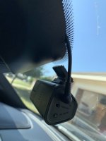
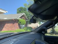
De-pin #1 and #4 if you need ignition or BAT inside the cab. I will probably use those for my dash cam.

View attachment 4286

@brutal,

EDIT: where are you finding these amazing wiring diagrams? None if this information came with my upfitter kit. Does the 2020 kit come with all of this information?

Here is a link to the wiring diagrams.

Please confirm I am interpreting the diagrams and your explanation correctly:

The AUX 6 button in the cab powers pin 2 on the light gray AUX connector under the hood, but pin 2 is jumpered to pin 4 which goes back into the cab as G425 on a violet/yellow wire and terminates at the light gray port (known as "D" or Port_Upfitters_2 or D2621A_Body_D) which is located horizontally aligned with the headlight switch and CAN bus blocks, close to the firewall.

The upfitter kit comes with a gray connector (known as Jumper Port_Upfitters_2) that plugs into Port_Upfitters_2.
  • Pins 1 and 6 are jumpered with a red/white wire. Ignition power comes in on pin 6 and goes out on pin 1 which goes to the back of the truck (location "F") and terminates at "blunt cut wires." Pin 6 is on a 20A fuse at location 36.
  • Pin 2 is unused.
  • Pins 3 and 4 are jumpered with a pink/orange wire. Batter power comes in on pin 3 and goes out on pin 4 which goes to the back of the truck (location "F") and terminates at "blunt cut wires." Pin 3 is on a 20A fuse at location 45.
  • Pin 5 comes from pin 4 on light gray AUX port under the hood on a violet/yellow wire which is jumpered to pin 2 which connects to the AUX 6 button. Pin 5 is backed by a 40A fuse at location 37.
If you don't care about having ignition or battery power to the blunt cut wires at location "F", you can de-pin 1 and 4 (or just cut the jumpers).

This means AUX 6 can power something under the hood (connected to AUX light gray pin 2) and it can simultaneously power something in the cab connected to pin 5 on Port_Upfitters_2.

This also means AUX 1 to AUX 5 are not routed inside the cab, only AUX 6.
 
Last edited:

Brutal_HO

The Mad Irishman
Staff member
Joined
Feb 1, 2020
Messages
12,108
Reaction score
21,568
Location
Douglas County, CO
@brutal,

EDIT: where are you finding these amazing wiring diagrams? None if this information came with my upfitter kit. Does the 2020 kit come with all of this information?

Here is a link to the wiring diagrams.

Please confirm I am interpreting the diagrams and your explanation correctly:

The AUX 6 button in the cab powers pin 2 on the light gray AUX connector under the hood, but pin 2 is jumpered to pin 4 which goes back into the cab as G425 on a violet/yellow wire and terminates at the light gray port (known as "D" or Port_Upfitters_2 or D2621A_Body_D) which is located horizontally aligned with the headlight switch and CAN bus blocks, close to the firewall.

I'm adding that jumper from the AUX#6 pin to the G425 pass-through wire..


The upfitter kit comes with a gray connector (known as Jumper Port_Upfitters_2) that plugs into Port_Upfitters_2.
  • Pins 1 and 6 are jumpered with a red/white wire. Ignition power comes in on pin 6 and goes out on pin 1 which goes to the back of the truck (location "F") and terminates at "blunt cut wires." Pin 6 is on a 20A fuse at location 36.
  • Pin 2 is unused.
  • Pins 3 and 4 are jumpered with a pink/orange wire. Batter power comes in on pin 3 and goes out on pin 4 which goes to the back of the truck (location "F") and terminates at "blunt cut wires." Pin 3 is on a 20A fuse at location 45.
  • Pin 5 comes from pin 4 on light gray AUX port under the hood on a violet/yellow wire which is jumpered to pin 2 which connects to the AUX 6 button. Pin 5 is backed by a 40A fuse at location 37.
If you don't care about having ignition or battery power to the blunt cut wires at location "F", you can de-pin 1 and 4 (or just cut the jumpers).

This means AUX 6 can power something under the hood (connected to AUX light gray pin 2) and it can simultaneously power something in the cab connected to pin 5 on Port_Upfitters_2.

This also means AUX 1 to AUX 5 are not routed inside the cab, only AUX 6.

Mostly correct.

The crayon is my addition. I'm showing adding a jumper from AUX#6 to bring it back into the cab on the pass through wire G425. You could do the same with any AUX connection. You could also rewire the D connector to bring an AUX to the rear of the truck.
 

thestuarts

Well-Known Member
Joined
Jun 10, 2019
Messages
498
Reaction score
499
I'm adding that jumper from the AUX#6 pin to the G425 pass-through wire..


Mostly correct.

The crayon is my addition. I'm showing adding a jumper from AUX#6 to bring it back into the cab on the pass through wire G425. You could do the same with any AUX connection. You could also rewire the D connector to bring an AUX to the rear of the truck.

Now I understand.

I wish Ram made it easier to configure the AUX switches to power devices in the cab or at the rear of the truck, but at least it is possible to configure one of the AUX switches for the cab or the rear using G425 and Port_Upfitters_2.
 

Brutal_HO

The Mad Irishman
Staff member
Joined
Feb 1, 2020
Messages
12,108
Reaction score
21,568
Location
Douglas County, CO
I wish RAM made it easier to find fuses you drop in the engine bay checking to see if you got the right fuses.

The blister pack came open unexpectedly and two of the damn things disappeared in a flash.

At least they were the J-case fuses so no exposed leads.
 
Last edited:

carlrx7

Well-Known Member
Joined
Oct 20, 2019
Messages
320
Reaction score
286
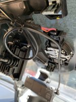
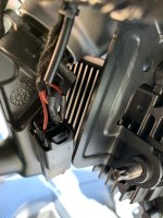
Why is there no interior fuse block in these trucks! I would prefer to use an add-a-circuit, but ended up tapping into the back of the mirror power. I tell you what, that plastic cover over the rain & radar sensors will test your faith. I was pretty sure that plastic was going snap or i was going to crack the windshield. Holy moly, its finished, no damage.

IMG_0940.jpg IMG_0938.jpg IMG_0934.jpg IMG_0933.jpg

-cb
 

John Jensen

Well-Known Member
Joined
Feb 11, 2020
Messages
1,201
Reaction score
1,054
Carl,
Nice work. You will be glad you did it this way. Much cleaner and looks better as well. I've always wired to the mirror leads with both my dashcams and radar detectors, never had a problem or fuse blown.
 

Nifty07

New Member
Joined
May 11, 2020
Messages
27
Reaction score
7
Been trying to look under the aux pdc but cant seem to find the clips to release the relay/fuse holder. I was looking to wire in some additional fuses/relays. Any clues??
 

SMK Shoe

Member
Joined
Oct 17, 2020
Messages
93
Reaction score
54
Just finished dropping the headliner to add some sound deadening matting and the cables for a front and rear dash cam. Have the power run down the drivers A pillar now need to find power. But at least the hard part is done.
 

MSundet

Active Member
Joined
Mar 14, 2020
Messages
197
Reaction score
171
Why is there no interior fuse block in these trucks! I would prefer to use an add-a-circuit, but ended up tapping into the back of the mirror power. I tell you what, that plastic cover over the rain & radar sensors will test your faith. I was pretty sure that plastic was going snap or i was going to crack the windshield. Holy moly, its finished, no damage.

View attachment 4311 View attachment 4310 View attachment 4309 View attachment 4308

-cb

Sent you a DM with questions !

Thanks


Sent from my iPhone using Tapatalk
 

HeavyCivil

New Member
Joined
Jan 8, 2021
Messages
1
Reaction score
2
Why is there no interior fuse block in these trucks! I would prefer to use an add-a-circuit, but ended up tapping into the back of the mirror power. I tell you what, that plastic cover over the rain & radar sensors will test your faith. I was pretty sure that plastic was going snap or i was going to crack the windshield. Holy moly, its finished, no damage.

View attachment 4311 View attachment 4310 View attachment 4309 View attachment 4308

-cb
Good afternoon. In your wiring setup, do you have switch power or constant on? I am in the process of wiring up my dash camera and want to have constant on so it records when parked and the ignition is off (at least until the settings turn off the camera due to battery voltage drop at 12.4V).

Also, did so much reading about the fuse panel on the 5thGen page and got my head straight about which fuse to run power from only to find out my 3500 didn’t have the fuse panel under the steering wheel like the 1500’s do...SMH...so now trying to establish ”plan B”.

Thanks in advance!
 

SMK Shoe

Member
Joined
Oct 17, 2020
Messages
93
Reaction score
54
Im in the same boat. Ran a forward and rear facing dash cam wiring under the headliner ( dropped it to add dynamat ) and ran wiring down the driver's side a Pillar to the dash. NOW, I gotta figure out where to get power. These new Rams are a electrical nightmare.
 

Brutal_HO

The Mad Irishman
Staff member
Joined
Feb 1, 2020
Messages
12,108
Reaction score
21,568
Location
Douglas County, CO
Im in the same boat. Ran a forward and rear facing dash cam wiring under the headliner ( dropped it to add dynamat ) and ran wiring down the driver's side a Pillar to the dash. NOW, I gotta figure out where to get power. These new Rams are a electrical nightmare.
Do you have the Aux switches?
 

SMK Shoe

Member
Joined
Oct 17, 2020
Messages
93
Reaction score
54
Ive got the aux switch's and was thinking of using the pass thru for power but with limited switches was thinking a hard wire would be a better option
 

Nifty07

New Member
Joined
May 11, 2020
Messages
27
Reaction score
7
Mine did not have the cabling from the aux switch wired through to the PDC. I ran a seven core trailer cable, spliced into the truck side of the Aux Switch assembly plug (XY125) and ran this to a number of automobile relays under the bonnet. I found I needed to run battery to the relay (combined the relays Common pin 86 contact and ran to battery via a 5amp fuse) and relay pin 85 to the respective Aux switch. When you press the Aux Switch it switches to ground.

I ran a 16mm common from the battery and ran this to blade ganged blade fuse holder. The other side of each fuse goes to its respective relay Common contacts (pin 30). The other relay contact (pin 87) goes to the lights, compressor, etc.

I picked up the cigarette lighter positive on the seventh wire which is used to switch ignition to an Anderson (via isolation relay) for the trailer. I ran a 16mm cable on the Anderson as it has a lithium in the caravan with a DC2DC charging unit drawing 40 amps. There is an ignition source under the main PDC (XY110A-33 PK/BG) if you wanted to use that as an ignition source. I found it harder to access so went with easy access. as I already had the dash access.

Dealer activated the switches and these are now programmable via commercial.

After reading this forum it made the task very simple. Thank you to all who contributed.


Below is how I wired the spot lights. I normally run with spot lights wired to high beam (XY110A-26 WH/GY) and to turn them off I press Aux Switch 6. If you want to change this to only attractive when Aux 6 switched on wire to the normally open contacts of relay 1 below (change 87A to 87).

When the Aux 6 switched to operate (off in my application), the high beam activates relays 2 & 3. One spot light to relay 2 and the other to relay 3 as they draw a bit of current.


Control Relay:

Switch​
Function​
Relay 1​
AUX 6Spots85
Battery via fuse86
Relay 2 & Relay 3 pin 8687A
R High BeamXY110A-26 WH/GY30


Spot Light left relay:

Switch​
Function​
Relay 2​
87A Relay 1high beam via aux86
Ground85
Spot Light Left87
F1 - 30ampPrimary Battery30


Spot Light right relay:

Switch​
Function​
Relay 3​
87A Relay 1high beam via aux86
Ground85
Spot Light Right87
F2 - 30ampPrimary Battery30
 

Nifty07

New Member
Joined
May 11, 2020
Messages
27
Reaction score
7
Sorry, above probably wrong thread.

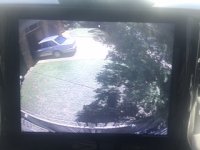
Yesterday Advanced ICE fitted their mapping which includes street and off road mapping. This also came with a trailer reversing camera option. As my Ram did not have the trailer reversing camera fitted I ticked that option. I ran the supplied cable from under the dash and wired this to the 12 pin trailer plug.

I now get a full screen trailer reversing camera view. I can press the Back Camera to see the tailgate camera. By pressing the Browse button I get a picture in window trailer reversing camera view which is fabulous. Sorry my picture of the screen is not very good (horrible). The image is same quality as the tailgate camera.

terailer reversing camera.jpeg
 

Cseybert

Well-Known Member
Joined
Jan 7, 2021
Messages
456
Reaction score
443
I’m really surprised it’s not an option on most vehicles nowadays. Would be great if it was for legal purposes.
 

Brutal_HO

The Mad Irishman
Staff member
Joined
Feb 1, 2020
Messages
12,108
Reaction score
21,568
Location
Douglas County, CO
Sorry, above probably wrong thread.

Yesterday Advanced ICE fitted their mapping which includes street and off road mapping. This also came with a trailer reversing camera option. As my Ram did not have the trailer reversing camera fitted I ticked that option. I ran the supplied cable from under the dash and wired this to the 12 pin trailer plug.

I now get a full screen trailer reversing camera view. I can press the Back Camera to see the tailgate camera. By pressing the Browse button I get a picture in window trailer reversing camera view which is fabulous. Sorry my picture of the screen is not very good (horrible). The image is same quality as the tailgate camera.

View attachment 11279

If you let me know what thread that post above belongs in, we can move it for you.
 

Brutal_HO

The Mad Irishman
Staff member
Joined
Feb 1, 2020
Messages
12,108
Reaction score
21,568
Location
Douglas County, CO
Ive got the aux switch's and was thinking of using the pass thru for power but with limited switches was thinking a hard wire would be a better option

I used my IGN+ and BAT+ from the jumper for the dash cam, but I'm going to add in a fuse block so I can also still bring IGN+ and BAT+ to the blunt cut wires in the back.

I used the pas-thru circuit to bring AUX6 back into the cab for my 2-LO box.

I found this one with 6 separate circuits that can be slaved together as needed. It actually measures on 5Hx2W.


1611984828212.png
 

Users who are viewing this thread

Top